Profibus inputand output units. The built-in microprocessor allows automatic
executionof the entire data transmission, thus relieving the PLC of real-time
tasks.
Data is exchanged between the PLC and the DPM01/ DPS01 printed circuit
boards via an 8-kbyte dual-port memory (DPM). The DPM is a memory which
can be simultaneously accessed by the PLC and the microprocessor of the
DPM01/DPS01 printed circuit boards.
The LK DPM/DPS01 are configured and commissioned via the SyCon system
configurator (see DOK-CONTRL-SYCON****DP-AW...). For configuration the
IKS0106 interface cable is required. The LK DPM01 PROFIBUS DP master
connection allows the connection of up to 32 PROFIBUS DP usesrs within one
bus segment. If several bus segments are connected to each other via a re‐
peater, a maximum of 125 slaves can be operated in the maximum configura‐
tion.
The LK DPM01 PROFIBUS DP master connection allows the connection of up
to 32 PROFIBUS DP users within a bus segment. If several bus segments are
connected to each other via a repeater, a maximum of 125 slaves can be op‐
erated in the maximum configuration. However, each repeater in use reduces
the maximum number of slaves within one segment, whereas no user address
is assigned to the repeater, as a passive user.
Depending on the transmission rate set in each case, line lengths of up to 1200
m can be realized between the Profibus DP users. The line length is reduced
to max. 200 m if the transmission rate is 1.5 MBaud and to 100 m if the trans‐
mission rate is 12 MBaud.
Slaves with inputs of a maximum of 244 bytes and outputs of a maximum of
244 bytes can be connected to the LK DPM01 master. The total of inputs and
outputs of all slaves must not exceed 512 bytes each.
The LK DPS01 slave must be configured in such a way that the total of the
inputs and/or outputs of the individual modules is a maximum of 244 bytes each.
Do ensure that the total of the inputs and outputs of all modules does not exceed
368 bytes.
In order to ensure proper functioning of the PROFIBUS interface,
only cables IKB0033 / IKB0034 or cables according to PROFIBUS
specification RS485 (cable type A) are to be used.
9.6.2 Setting I/O addresses
The bus address is set using the jumpers of plug board J2. The address line is
specified next to each jumper.
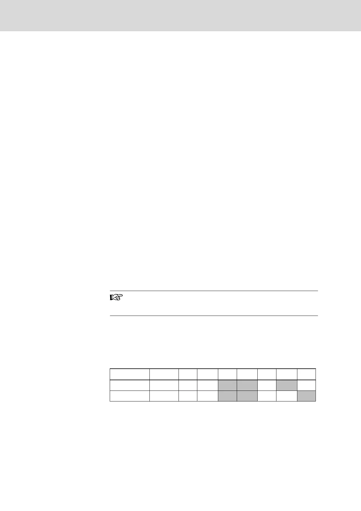
Depending on the additional slot, the addresses must be set as follows (X =
jumper plugged):
Connection Address A19 A18 A17 A16 A15 A14 A13
Master $CA000 X X X
Slave $CC000 X X X
Fig.9-22: Setting the module type
9.6.3 Status and Diagnosis Information
While switching on the DPM01/DPS01 printed circuit boards, they perform a
self-test. After the initialization phase of this test (2 to 3 seconds), the two L EDs
ERR and STA turn dark, and the yellow RDY LED lights if the test is successfully
completed . If not, the RDY LED starts flashing, and the processing of the pro‐
122/135 Bosch Rexroth AG | Electric Drives
and Controls
Rexroth MTA 200 | Project Planning Manual
PLC Modules MTS-P01.2 and MTS-P02.2

 Loading...