Device type Memory assignment in the input/output image
BTM 15 Depending on the configuration
2 bytes for digital I/Os (always assigned)
2 additional bytes for each module (except handwheel)
4 additional bytes for handwheel module
BTM 16 14 bytes
BTA 20 6 bytes
Fig.9-6: Memory requirements of the operating devices
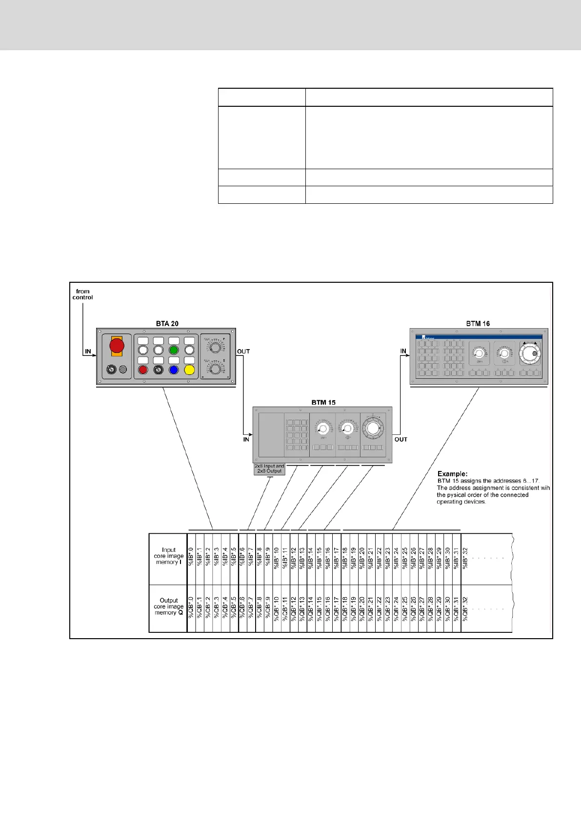
Depending on the physical order of the operating devices connected tothe BT
bus, the device addresses are assigned in the input and output image memory
without any gaps according to the storage requirements of the operating devi‐
ces. The example (fig. 9-7 "Memory assignment in BT bus" on page 113)
illustrates the principle of the memory assignment of the BT bus.
Fig.9-7: Memory assignment in BT bus
9.4 Commissioning
9.4.1 Installation
Plug the MTS-P module into an unoccupied ISA bus slot of your industrial PC.
If possible, fasten the module using the supplied holder to prevent the card from
Project Planning Manual | Rexroth MTA 200 Electric Drives
and Controls
| Bosch Rexroth AG 113/135
PLC Modules MTS-P01.2 and MTS-P02.2

 Loading...