3-69
Confidential
9.24 Control Panel ASSY
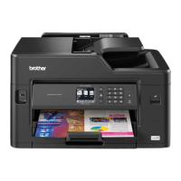
(1) Release the Lock of the connector and remove the Panel flat cable from the Main
PCB.
(2) Disconnect the four Flat cables from the Main PCB.
(3) Disconnect the five Connectors from the Main PCB.
Fig. 3-63
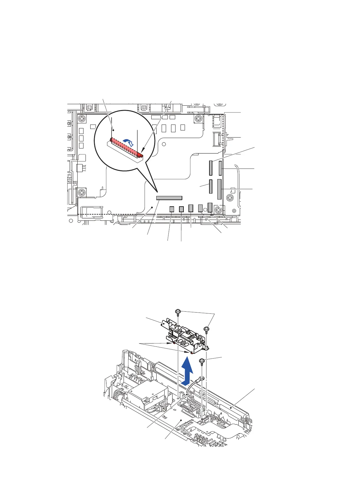
(4) Release all the wiring attached to the Main PCB harness hold.
(5) Remove the screw (SCREW CUP M3x6) and remove the FG wire from the Main
PCB frame base.
(6) Remove the two screws (TAPTITE CUP B M3x10) and while releasing two Hooks,
remove the Main PCB harness hold from the Main PCB frame base.
Fig. 3-64
Lock
Main PCB
Panel flat cable
Carriage flat cable
Carriage flat cable
Ink sensor flat cable
Modem PCB
ASF encoder sensor harness
Cap cam harness
Speaker harness
Panel flat cable
Maintenance
Ink cartridge cover sensor harness
cam harness
flat cable
Main PCB harness hold
FG wire
Main PCB frame base
Control panel ASSY
TAPTITE CUP B M3x10
SCREW CUP M3x6
Hooks
 Loading...