3-125
Confidential
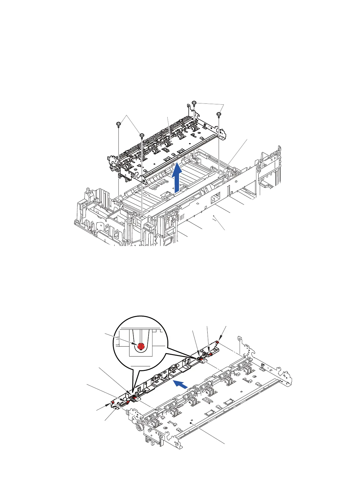
9.57 Registration Sensor PCB
(1) Release the wiring of the Registration sensor harness.
(2) Remove the four screws (TAPTITE CUP B M3x10) and remove the Frame base
ASSY from the Lower cover.
Assembling Note: When tightening the four screws (TAPTITE CUP B M3x10), tighten
them in the order shown in the figure.
Fig. 3-158
(3) Release the two Hooks A and two Bosses and remove the DX paper guide from
the Frame base ASSY.
(4) Release the wiring of the Registration sensor harness.
Assembling Note: When assembling the DX paper guide, be sure there is no
looseness of the Harness.
Also, the two Hooks B at the right and left sides must be inserted
properly.
Fig. 3-159
TAPTITE CUP B M3x10
Frame base ASSY
TAPTITE CUP B M3x10
1
2
4
3
Lower cover
Paper feed arm frame ASSY
Frame base ASSY
DX paper guide
Boss
Hook B
Boss
Boss
Hook A
Hook A
Hook B

 Loading...