19
Networks
Specifications
1
Specifications
Remote Control Network
The remote control system network wire colors
are as follows:
Grounding Requirements
The remote control network should be grounded
at a SINGLE location. This is normally done at the
network power cable connection and should be
robustly connected to the boat’s grounding sys-
tem.
There must be no other ground connections on
the remote control network to avoid ground loops,
which can cause problems with system perfor-
mance.
Maximum Number of Devices
A maximum of 10 devices can be attached to the
remote control network. The number of devices is
limited by the number of hub connections.
6-port hubs are NOT required in all installations.
Refer to Diagrams on p. 107.
IMPORTANT: Only connect remote control com-
ponents to the remote control network.
Open Device Connectors
Install protective covers on “open” or unused
device connectors.
Remote Control Network Requirements
The remote control network requires the following
components:
• One remote control
• One OFF-ON-START key switch or
one master power key switch
• One START/STOP switch for each engine (mul-
tiple engine installations only)
• One trim switch panel (3, or 4 engines only)
• 6-port hub (see installation diagrams)
• One backbone buss cable
• One, two, three, or four outboards
Installations using an optional second station
requires the following additional components:
• One remote control
• 6-port hub (see installation diagrams)
• One emergency stop switch
• One START/STOP switch for each engine
• One trim switch panel (3, or 4 engine installa-
tions only)
Load Equivalency
The Engine Management Module (EMM) on Evin-
rude E-TEC G2 outboards has a load equivalency
number of 1. Less than 50 mA of the network’s
(CAN) power is used by the EMM.
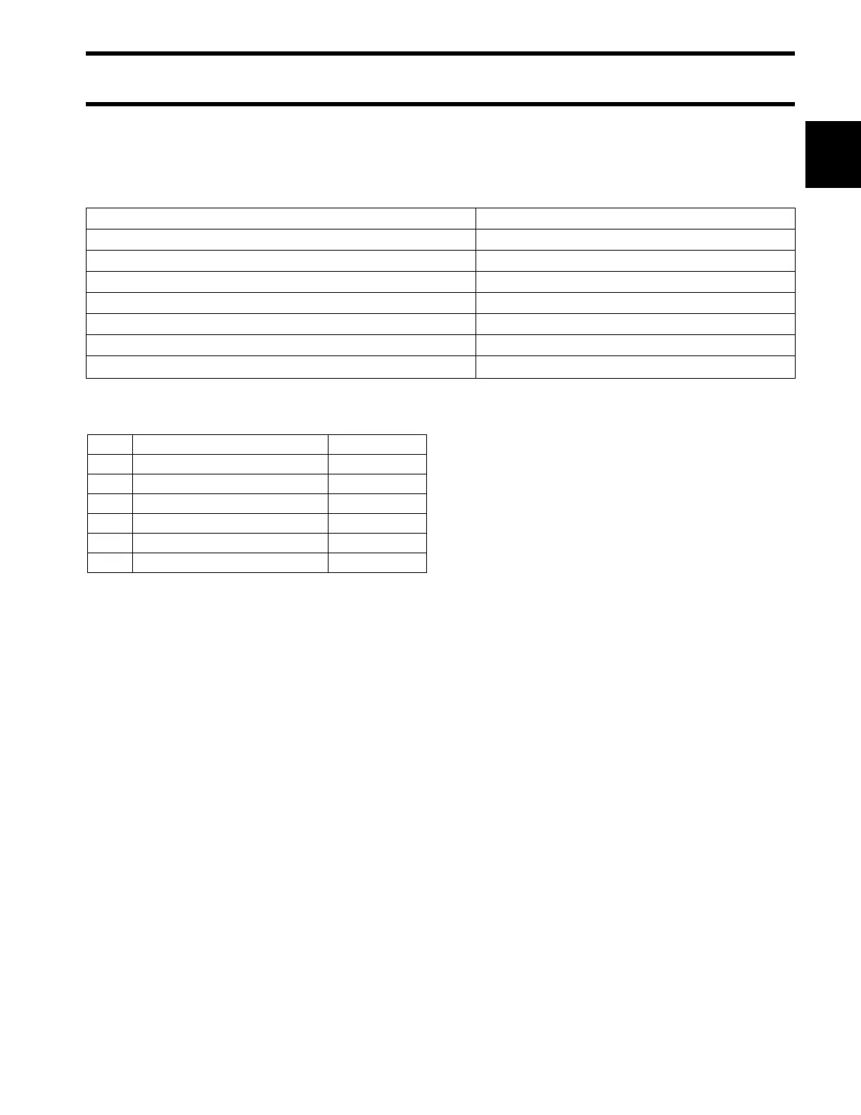
Supply Voltage (Boat System) 9 to 18 VDC
Operating Voltage (Remote Control Network) 5 VDC
Engine Control 1, 2, 3, or 4 outboards
Reverse Polarity Protection Continuous
Fuse, Network Power Cable 10 Amp, ATO Type, P/N 967545
Network Interface Proprietary
Operating Temperature Range -13° to 167° F (-25° to 75° C)
Maximum Current Draw
(with Master Power Switch OFF)
10µA
Pin Control Wire Designation Wire Color
1 Wake Up Black/White
2 Power supply (+VDC) Red
3 Ground (–VDC) Black
4 Data HI (Signal) White
5 Data LOW (Signal) Blue
6 Stop Circuit Black/Yellow

 Loading...