DPC Redundancy LED States
The Redundancy LED on the DPC/UDPC or /DPC2/UDPC2 indicates that software is loaded on the card, but
it is serving as a standby component. DPC/UDPCs or /DPC2/UDPC2s support n:1 redundancy; the Redundancy
LED should be green on only one DPC/UDPC or /DPC2/UDPC2 for normal system operation.
The possible states for this LED are described in the following table. If the LED is not green, use the
troubleshooting information in the table to diagnose the problem.
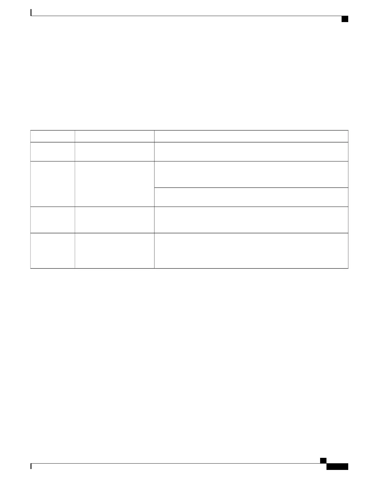
Table 24: DPC Redundancy LED States
TroubleshootingDescriptionColor
None needed. There is at least one DPC/UDPC or /DPC2/UDPC2 in Standby
mode.
Card is in standby mode.Green
Check the status of the other DPC/UDPCs or /DPC2/UDPC2s. If one DPC/UDPC
or /DPC2/UDPC2 has failed or has been removed from the chassis, the system
can continue to function but redundancy is compromised.
Card is not backed up by a
standby DPC.
Amber
Refer to Monitoring the System for information on determining the status of the
DPC/UDPC or /DPC2/UDPC2 and system software processes.
Refer to Monitoring the System for information on determining the status of the
DPC/UDPC or /DPC2/UDPC2 and system software processes.
Tasks or processes being
migrated from an active DPC to
the standby DPC.
Blinking Amber
Verify that the Run/Fail LED is green. If so, the card is receiving power and
POST results are positive. If it is off, refer to DPC Run/Fail LED States, on
page 207 for troubleshooting information.
Card is not receiving power.
OR
Card has failed.
None
Checking the LEDs on the FSC
Each FSC is equipped with the following LEDs as shown in the accompanying figure:
•
Run/Fail
•
Active
•
Redundancy
•
Drive 1 Activity
ASR 5500 System Administration Guide, StarOS Release 21.4
209
Troubleshooting
Checking the LEDs on the FSC

 Loading...


