EasyManua.ls Logo

Cisco UCS X9508 User Manual

Cisco UCS X9508
132 pages
To Next Page IconTo Next Page
To Previous Page IconTo Previous Page
Page #119 background image
Specifications for the Cisco UCS X9508 Chassis Power Supply
Units
Table 9: AC-input Titanium Power Supply (N20-PAC5-2800W) Specifications
SpecificationDescription
Voltage Range 100-127 VAC, 200-240 VAC Nominal
(range: 90-140 VAC, 180-264 VAC)
AC-input voltage
50 to 60 Hz nominal (range: 47 to 63 Hz)AC-input frequency
18 A @ 90 VAC
18 A @ 180 VAC
Maximum AC-input current
3200 VA at 230 VACMaximum input VA
2800 W @ 200-240 VAC Nominal
1400 W @ 100-127 VAC Nominal
Maximum output power per power supply
35 A (sub cycle duration)Maximum inrush current
10 ms @ 1400 W
10 ms @ 2800 W
Minimum hold up time
54 VDCPower supply main output voltage
3.4 VPower supply standby voltage
80+ Titanium CertifiedEfficiency Rating
IEC320 C20
System input power connectors are located in the
chassis PEMs, not on the power supply
Input connector
For information about supported power cords, see Technical Specifications, on page 107.
Supported AC Power Cords and Plugs
The AC power connectors on the chassis PEM use an IEC 320 C20 socket. Each chassis power supply has a
separate power cord. The power cord that you use to connect the power supply units to an AC power source
will have an IEC 320 C19 plug on one end and on the other end one that conforms to the AC power outlet
specifications for your country. See the following table to determine which cord to order for your chassis
power supply units. When you determine which power cord you need to order, you can verify that its plugs
conform to the power outlets for your facility by clicking on its reference link.
The jumper power cords, for use in racks, are available as an optional alternative to the standard power cords.
The optional jumper power cords have an IEC C19 connector (such as a Cisco RP Series PEM) on the end
Cisco UCS X9508 Server Chassis Installation Guide
111
Technical Specifications
Specifications for the Cisco UCS X9508 Chassis Power Supply Units

Table of Contents

Other manuals for Cisco UCS X9508

Question and Answer IconNeed help?

Do you have a question about the Cisco UCS X9508 and is the answer not in the manual?

Cisco UCS X9508 Specifications

General IconGeneral
Total Slots8
Supported Server NodesCisco UCS X-Series Server Nodes
Number of Half-Width Slots8
Number of Full-Width Slots0
Storage OptionsDependent on server node configuration
Power SuppliesUp to 4 power supplies
Power Supply RedundancyN+1 redundancy
CoolingHot-swappable fans
Chassis ManagementCisco UCS Manager
Dimensions (H x W x D)32.0 in (81.3 cm)

Summary

Overview

System Overview

Describes the Cisco UCS X9508 Server Chassis and its components within the Cisco Unified Computing System.

Features and Benefits

Details the advantages and capabilities of the Cisco UCS X9508 server chassis.

Chassis Components

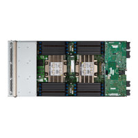
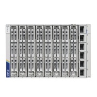
Provides an overview of the various physical components of the Cisco UCS X9508 chassis.

Intelligent Fabric Modules

Explains the functions and types of Intelligent Fabric Modules (IFMs) in the chassis.

Power Supplies

Covers the AC power supplies (PSUs) supported by the chassis and their configurations.

LEDs

Explains the function and location of LEDs on the chassis and its components.

Installation

Installation Notes and Warnings for the Cisco UCS X9508 Server Chassis

Provides crucial safety instructions and warnings before installing the chassis.

Rack Requirements

Specifies the necessary requirements for installing the chassis in a rack.

Handling the Chassis

Provides instructions on how to safely handle the server chassis.

Installing the Chassis

Guides the user through the process of installing the chassis into the rack.

Inserting the Chassis into the Rack

Explains how to place the chassis into the installed rack rails.

Removing the Chassis from a Rack

Provides steps to safely remove the chassis from the rack.

Installing and Removing Components

Components

Introduces the components that can be installed or removed from the chassis.

Installing and Removing a Compute Node

Guides on installing and removing compute nodes.

Installing and Removing Power Supplies

Instructions for installing and removing power supply units (PSUs).

Replacing the Power Entry Modules (PEMs)

Guides on replacing the Power Entry Modules (PEMs).

Installing and Removing a Fan Module

Covers installing and removing fan modules.

Installing and Removing an Intelligent Fabric Module

Guides on installing and removing Intelligent Fabric Modules (IFMs).

Recycling Printed Circuit Boards

Information on how to recycle printed circuit boards.

Technical Specifications

Chassis Specifications

Lists the physical dimensions and capacities of the chassis.

Environmental Specifications

Provides environmental operating conditions for the chassis.

Specifications for the Cisco UCS X9508 Chassis Power Supply Units

Lists the technical specifications for the chassis power supply units.

Site Planning and Maintenance Records

Site Preparation Checklist

A checklist for preparing the installation site.

Contact and Site Information

Worksheet to record contact and site details.

Chassis and Module Information

Worksheet to record chassis and module serial numbers.

Related product manuals