CHAPTER 3
Installing and Removing Components
This chapter describes how to remove components from the chassis and how to install components into the
chassis. This section contains the following section:
• Components, on page 57
• Installing and Removing a Compute Node Blank, on page 63
• Installing and Removing a Compute Node, on page 67
• Installing and Removing Power Supplies, on page 70
• Replacing a PSU Blank, on page 73
• Replacing the PSU Keying Bracket, on page 76
• Replacing the Power Entry Modules (PEMs), on page 79
• Installing and Removing a Fan Module, on page 84
• Installing and Removing a Rear Module's Fan, on page 87
• Installing and Removing an Intelligent Fabric Module, on page 90
• Recycling Printed Circuit Boards, on page 93
Components
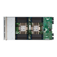
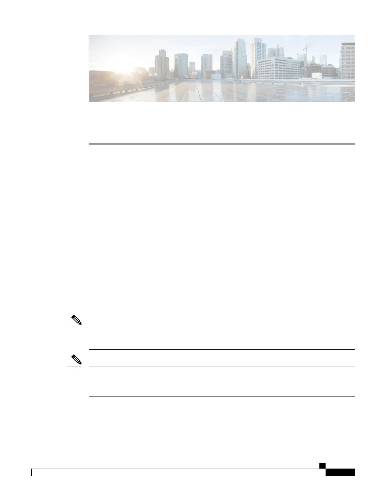
The following figure shows an empty Cisco UCS X9508 server chassis and identifies the front, back, and
module slots.
Before you remove or install components, please ensure that all software applications are shutdown and
management software is in a good state.
Note
Whenever you remove a module from the chassis for an extended period of time, always replace the module
with the appropriate blank panel. Failing to do so can result in heating and EMI issues. Blank panels can be
ordered from Cisco Systems.
Note
Cisco UCS X9508 Server Chassis Installation Guide
57
 Loading...