Home
ComAp
Controller
InteliLite 4 AMF 20
ComAp InteliLite 4 AMF 20 User Manual
5
of 1
of 1 rating
620 pages
Give review
Manual
Specs
To Next Page
To Next Page
To Previous Page
To Previous Page
Loading...
InteliLite4
AMF20
Global
Guide
19
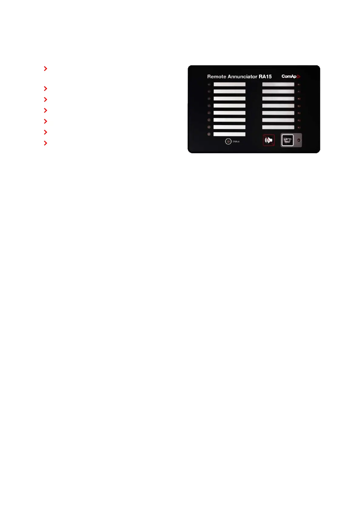
2.6.6
IGL-RA15
Remote
annunciator.
15
programmable
LEDs
with
configurable
colors
red-green-yellow
Lamp
test
function
with
status
LED
Customizable
labels
Local
horn
output
Maximal
distance
200
m
from
the
controller
Up
to
4
units
can
be
connected
to
the
controller
UL
certified
6
back
to
System
overview
18
20
Table of Contents
Table of Contents
2
Legal Notice
5
Document Information
5
About this Global Guide
5
Clarification of Notation
5
General Security Recommendations and Set of Measures
6
Used Open Source Software
7
General Warnings
7
Remote Control and Programming
7
SW and HW Versions Compatibility
7
Dangerous Voltage
8
Adjusting the Setpoints
8
Functions and Protections
8
Document History
9
Certifications and Standards
9
Symbols in this Manual
10
System Overview
11
General Description
11
The Key Features of Intelilite
11
True RMS Measurement
11
Configurability and Monitoring
11
Supported Configuration and Monitoring Tools
11
Configuration Parts
12
PC Tools
13
Inteliconfig
13
Websupervisor
13
Winscope
14
Inteliscada
14
Plug-In Modules
15
CM3-Ethernet
15
Cm2-4G-Gps
15
CM-Rs232-485
15
Em-Bio8-Efcp
16
CAN Modules
16
Inteli IO8/8
16
Inteli AIN8
17
Inteli AIN8TC
17
Igs-Ptm
18
Inteli AIO9/1
18
Igl-Ra15
19
Applications Overview
20
AMF - Automatic Mains Failure Start
20
MRS - Manual Remote Start
21
Installation and Wiring
22
Package Content
22
Controller Installation
22
Dimensions
22
Mounting
23
Terminal Diagram
24
Recommended Wiring
25
General
26
Power Supply
27
Example of AMF Wiring
27
Grounding
27
Measurement Wiring
28
Magnetic Pick-Up
48
Binary Inputs
49
Binary Outputs
50
E-Stop
51
Analog Inputs
51
CAN Bus and RS485 Wiring
53
Installation
58
Plug-In Module Installation
58
Usb Host
58
Usb
58
Maintenance
59
Backup Battery Replacement
59
Controller Setup
61
Default Configuration
61
Binary Inputs
61
Binary Outputs
61
Analog Inputs
61
Controller Configuration and PC Tools Connection
62
Usb
62
Rs232/Rs485
63
Ethernet
64
Operator Guide
71
Front Panel Elements
71
Display Screens and Pages Structure
73
Browsing Alarms
86
Login
87
Production Mode
90
Information Screen
91
Language Selection
93
Display Contrast Adjustment
94
IL4-RD Firmware Installation
95
General Description
95
Remote Display
95
Interconnection Variants
96
Wiring
96
Connection Process
97
Connection Troubleshooting
98
Function Description
98
Firmware Compatibility
99
Functions
100
Operating Modes
100
Start-Stop Sequence
102
Engine Start
104
AMF Operation
108
Connecting to Load
108
MRS Operation
108
Stabilization
108
Engine Cool down and Stop
111
Gen-Set Operation States
111
Additional Running Engine Indications
114
History Log
114
Breaker Control
116
Protections
119
Exercise Timers
134
Voltage Phase Sequence Detection
140
Load Shedding
141
Dummy Load
142
Sensor Curves
143
Plc
145
After-Treatment Support
151
Geo-Fencing
151
Alternate Configuration
156
USB Host
157
E-Stop
161
Firewall
161
ECU Frequency Selection
162
User Setpoints
162
Types of Interfaces
164
User Management and Data Access Control
164
User Accounts
165
Managing Accounts
167
Account Break Protection
172
Access to Controller Data
173
Cybernetic Security
173
Communication
178
Direct Communication
178
Remote Communication
179
Connection to 3Rd Party Systems
184
Snmp
184
Modbus-Rtu, Modbus/Tcp
186
Technical Data
198
Appendix
199
Controller Objects
199
List of Controller Objects Types
199
Setpoints
199
Maximum Cranking Time
226
Comm Object
227
Config Level Advanced
227
Setpoint Group Engine Settings
227
Setpoint Group Range [Units] Default Value Step
227
Setpoint Visibility Always Description
227
Comm Object
228
Back to List of Setpoints
237
Config Level Advanced Setpoint Visibility Always Description
240
Alternative Config no
246
Back to List of Setpoints
246
Cranking Attempts
246
Related Applications AMF, MRS
246
Related FW
246
Values
387
List of Values
388
DPF Soot Load
399
Requested RPM
399
Speed Request
399
DEF Level
400
DPF Ash Load
400
Group: Generator
400
Nominal Current
402
Nominal Power
402
Nominal Voltage
402
Group: Load
403
Load P
403
Load P L1
403
Load P L2
403
Load P L3
403
Load Q
403
Load Q L1
404
Load Q L2
404
Load Q L3
404
Load S
404
Load S L1
404
Load Character L2
406
Load Power Factor L2
406
Load Power Factor L3
406
Load Character L3
407
Load Current L1
407
Load Current L3
407
Load Load Current L2
407
Group: Mains
408
Mains Frequency
408
Mains Voltage L1-N
408
Battery Volts
409
Mains Voltage L2-L3
409
Binary Inputs
410
Logical Binary Inputs
437
Logical Binary Outputs
464
Logical Binary Outputs Alphabetically
465
ECU Comm OK
473
ECU Red Lamp
474
ECU Run Stop
475
Electrical Alarm
475
Fuel Pump
477
Fuel Solenoid
477
GCB off Coil
481
GCB on Coil
482
GCB UV Coil
482
Gen-Set Active
483
Glow Plugs
484
Prestart
484
Starter
484
5
Based on 1 rating
Ask a question
Give review
Questions and Answers:
Need help?
Do you have a question about the ComAp InteliLite 4 AMF 20 and is the answer not in the manual?
Ask a question
ComAp InteliLite 4 AMF 20 Specifications
General
Brand
ComAp
Model
InteliLite 4 AMF 20
Category
Controller
Language
English
Related product manuals
ComAp InteliLite NT AMF 25
9 pages
ComAp InteliLite NT AMF Series
84 pages
ComAp InteliLite 9
401 pages
ComAp InteliLite MRS16
632 pages
ComAp InteliLite MRS11
65 pages
ComAp InteliLite MRS15
65 pages
ComAp InteliLite AMF25
735 pages
ComAp intelilite nt amf20
145 pages
ComAp intelilite nt amf25
145 pages
ComAp InteliLite4 AMF20
31 pages
ComAp InteliLite4 AMF25
31 pages
ComAp InteliSys NT
44 pages

 Loading...