InteliLite4 AMF20 Global Guide
474
Related FW 1.3.0 Related applications AMF,MRS
Comm object 116
Description
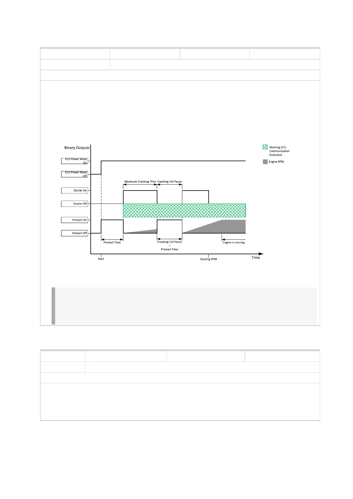
This output is to be used for control of "keyswitch" input of an ECU. If the particular ECU does not have
keyswitch or a similar input, it can be used for control of DC power for the ECU.
The output is activated together with PRESTART (PAGE 496) and remains active for the entire duration that
the engine is running. It is deactivated at the moment that the engine comes to a stop (i.e. together with the
FUEL SOLENOID (PAGE 477)).
Image 8.31 ECU Power Relay
IMPORTANT: This LBO also affects evaluation of Sd ECU Communication Fail (page 559) or
Wrn ECU Communication Fail (page 532) alarms. With configured LBO ECU Power Relay,
these alarms are evaluated only when this LBO is active. Without configured LBO ECU
Power Relay, these alarm are evaluated all the time.
ECU Power Relay
6 back to Logical binary outputs alphabetically
Related FW 1.3.0 Related applications AMF,MRS
Comm object 350
Description
This output is active when the ECU sends an active “red lamp” flag, i.e. it has detected a critical
malfunction and the engine should not be operated until a service check is performed. This flag is taken
from the DM1 frame on standard J1939 ECUs. Some ECUs provide this flag in their own proprietary
frames and some do not provide the flag at all.
ECU Red Lamp
6 back to Logical binary outputs alphabetically

 Loading...