2 Hardware Installation D-Link Smart Managed Switch User Manual
16
• When connecting or disconnecting power to hot-pluggable power supplies, if offered with your system,
observe the following guidelines:
Install the power supply before connecting the power cable to the power supply.
Unplug the power cable before removing the power supply.
If the system has multiple sources of power, disconnect power from the system by unplugging all
power cables from the power supplies.
• Move products with care; ensure that all casters and/or stabilizers are firmly connected to the system.
Avoid sudden stops and uneven surfaces.
Step 1: Unpacking
Open the shipping carton and carefully unpack its contents. Please consult the packing list located in the
User Manual to make sure all items are present and undamaged. If any item is missing or damaged, please
contact your local D-Link reseller for replacement.
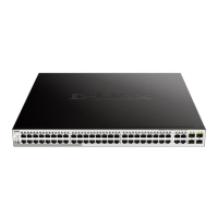
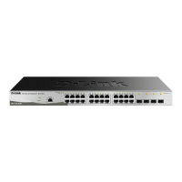
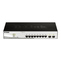
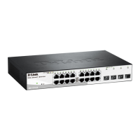
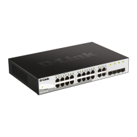
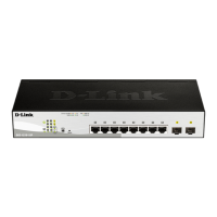
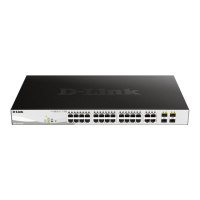
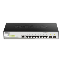
One D-Link DGS-1210 Smart Managed Switch
One Multilingual Getting Started Guide
User Guide CD
Power cord and Power Cord Retainer or external power adapter(DGS-1210-10P only)
Rack-mount kit and rubber feet
If any item is found missing or damaged, please contact the local reseller for replacement.
Step 2: Switch Installation
For safe switch installation and operation, it is recommended that you:
Visually inspect the power cord to see that it is secured fully to the AC power connector.
Make sure that there is proper heat dissipation and adequate ventilation around the switch.
Do not place heavy objects on the switch.
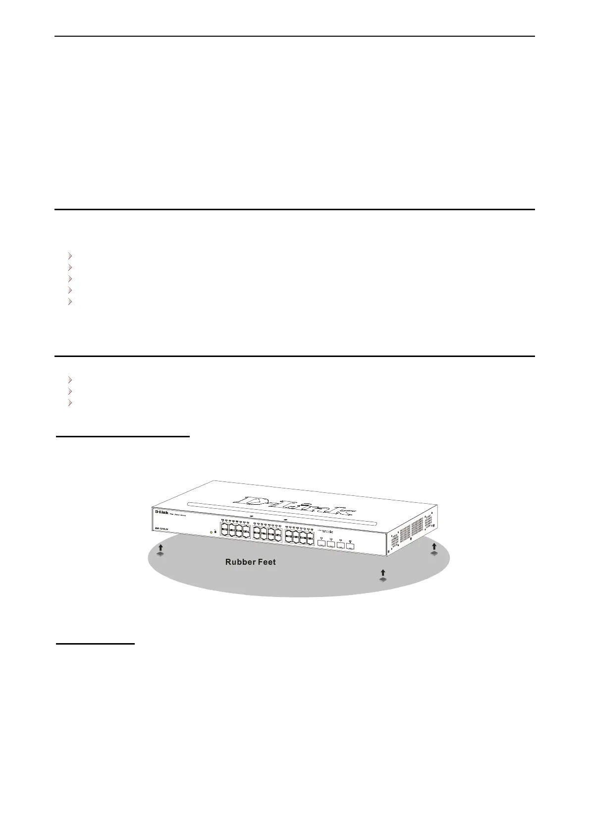
Desktop or Shelf Installation
When installing the switch on a desktop or shelf, the rubber feet included with the device must be attached
on the bottom at each corner of the device’s base. Allow enough ventilation space between the device and
the objects around it.
Figure 2.1 – Attach the adhesive rubber pads to the bottom
Rack Installation
The switch can be mounted in an EIA standard size 19-inch rack, which can be placed in a wiring closet with
other equipment. To install, attach the mounting brackets to the switch’s side panels (one on each side) and
secure them with the screws provided (please note that these brackets are not designed for palm size
switches).
 Loading...