Content
Introduction.........................................................................................4
Application..........................................................................................5
Installation ..........................................................................................7
Optional installations................................................................................7
Setting up the system ...............................................................................8
Removing units from a Danfoss Icon™ Master Controller 24V system..................................8
Connecting more Danfoss Icon™ Master Controllers in a system . . . . . . . . . . . . . . . . . . . . . . . . . . . . . . . . . . . . . .9
Test procedures for multiple Danfoss Icon™ Controllers in a system ...................................9
Slave type denition...............................................................................10
Reset or replace a Danfoss Icon™ Master Controller 24V ............................................10
Trouble shooting ..................................................................................10
Hydraulic balance .................................................................................11
Add-on Modules ..................................................................................12
Technical data.....................................................................................12
Introduction
Danfoss Icon™ is a modular heating system for
individual room control. It can be congured as
a wired or wireless system or as a combination, if
required.
The center of the system is the Danfoss Icon™
Master Controller 24V, which congures and ties
the system together.
Installation and set-up of the Danfoss Icon™ Master
Controller 24V is easy and described in the ncluded
materials:
• The Quick Guide shows the most common
installation with step-by-step illustrations, wired
installation on one side and wireless on the other.
• The Installation Guide describes the User
Interface, installation in details and set-up in
more complex systems.
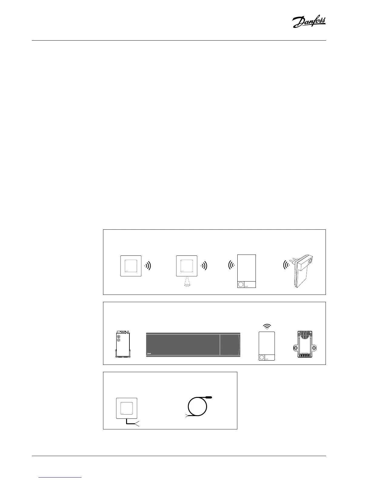
The Danfoss Icon™ family
Wireless system components
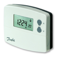
Wireless Display
088U1081
Wireless Display
088U1082
Infrared
Radio Module
088U1103
Repeater
088U1102
Common system components
Expansion Module
088U1100
Master Controller 24V
088U107x (multiple versions)
App Module
088U1101
Dew Point Sensor
088U0251
24V system components
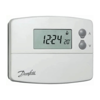
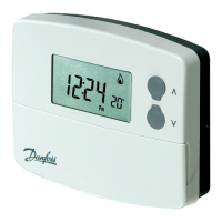
24V Display
088U105x (multiple versions)
24V
47 k Floor Sensor
088U1110
4 | © Danfoss | FEC | 2019.02
 Loading...