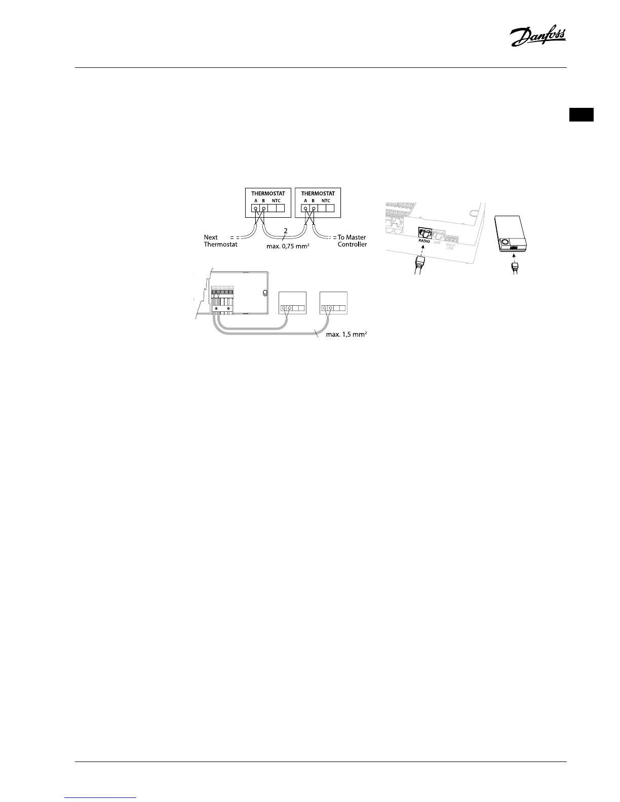
If wireless installation
Note! Disconnect power before wiring!
Connect a Radio Module, code no. 088U1103.
The Radio Module is required, when wireless ther-
mostats are installed. The radio module is supplied
with a 2m patch cable. A longer cable (max. 15m)
can be used if necessary.
One Radio Module must be tted to each Danfoss
Icon™ Master Controller 24V in systems with more
Master Controllers.
088U1103
As a special feature, it is possible to include wired
thermostats in a wireless system.
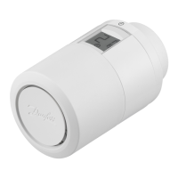
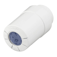
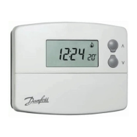
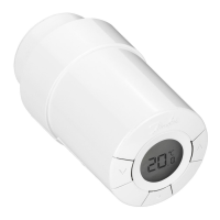
For installation of wireless thermostats and actua-
tors, please refer to the Wireless Quick Guide sec-
tions B2, B3, B4 and C1.
Optional
installations
Installation of App Module,
code no. 088U1101
The App Module is required, when app function-
ality is wanted. For inclusion in a wireless network
(Wi-Fi), please refer to the App Module installation
guide. In systems with more Danfoss Icon™ Master
Controllers only one App Module is required, and it
can be added to any of the Master Controllers.
Wiring a pump
PWR1 output is intended for usage in installations
where a circulation pump is present in the system.
The PWR1 output has a live 230 V output (max. 100
W), which is activated when heat is demanded by
at least one thermostat. When no heat is demanded
from any thermostat the PWR1 output will be
turned o to save energy.
When heat is demanded the output will be acti-
vated with a delay of 180 sec. to prevent the pump
from running without being able to generate ow
due to the delay on the actuators in the heating
circuits.
Wiring a potential free relay
A potential free relay can be used e.g. to activate
heat demand/production from a boiler.
It is recommended to use the potential free relay as
heat demand signal for all boilers with appropriate
inputs available.
For boilers with 0-10 V modulation it is not possible
to use the heat demand signal from the Danfoss
Icon™ Master Controller 24V.
Please note that some combi-boilers may have hot
water prioritization, which can cause heat produc-
tion of the system to be delayed.
Installation of Expansion Module,
code no. 088U1100.
Note! Disconnect power before inserting the
Expansion Module.
Slide of the cover and insert the Expansion Module.
Follow the supplied instructions.
Note! If an Expansion Module is added to a system
with multiple Master Controllers, it must be installed
on the System Master.
Installation of a Floor Sensor (if 24V thermo-
stat), code no. 088U1110.
For installation of a oor sensor, please refer to in-
structions supplied with the thermostat.
Rooms with both oor heating and radiators
controlled by one thermostat.
It is possible to have a mixed application with both
radiators and oor heating controlled by the same
Danfoss Icon™ room thermostat, if
• The thermostat has a oor sensor set up for “dual
mode“ on the thermostat (set “DU” mode in
installer menu on thermostat).
• The radiator has it’s ow controlled by an
actuator.
• Remember to set correct emitter type for relevant
outputs in said room.
In this application, the oor sensor is only used to
assure a min. oor temperature (if necessary, a max.
oor temperature can be set).
The built-in sensor is used to control the room
temperature by the assigned radiator output (the
fastest of the two output types).
Note! Only Danfoss Icon™ room thermostats with
oor sensor are supported.
VIMCG30F | 088N3678 | 7
© Danfoss | FEC | 2019.02