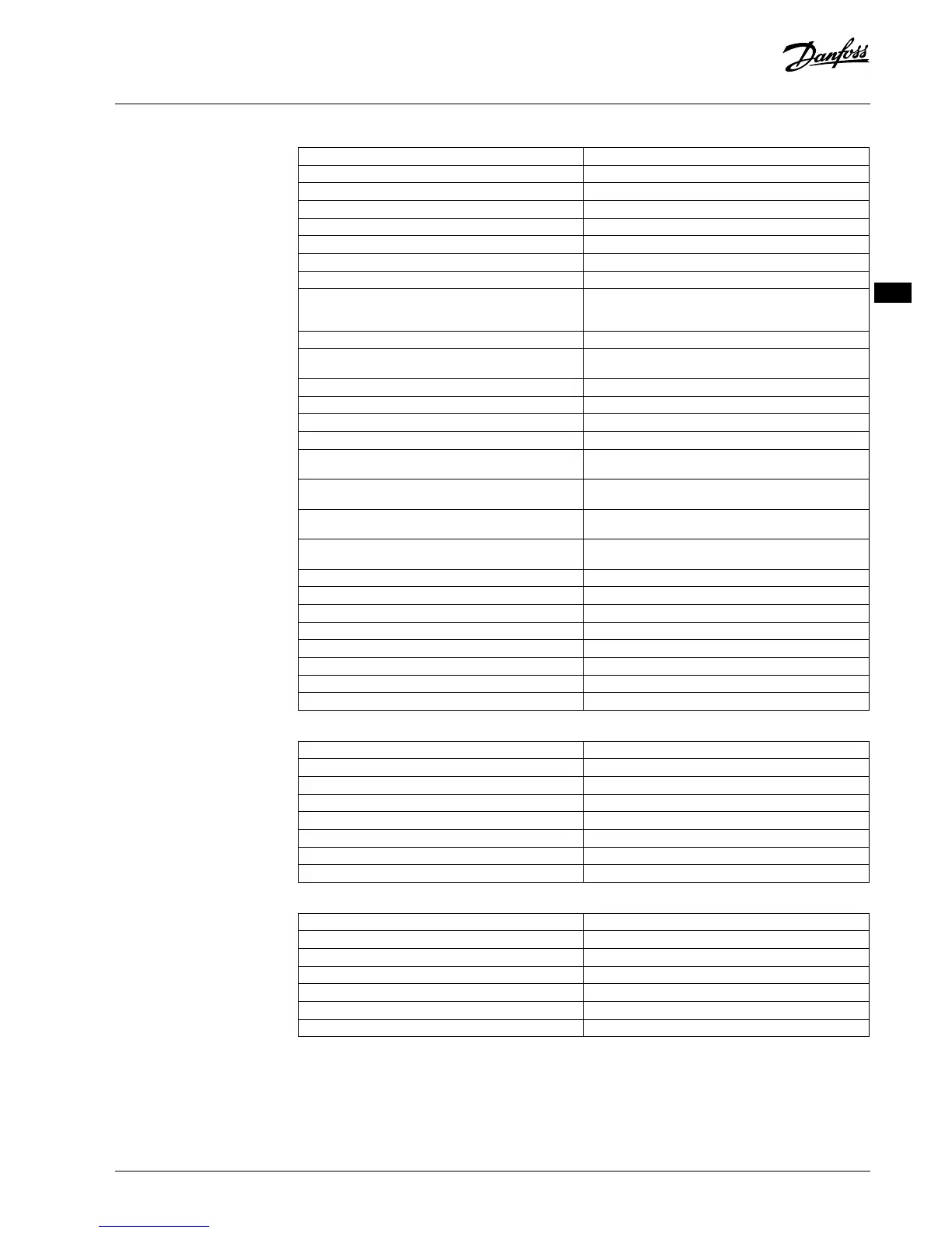
Hoofdregelaar 24 V en uitbreidingsmodule (optioneel)
Voedingsspanning 220-240 VAC
Voedingsfrequentie 50/60 Hz
Uitgangsspanning, servomotoren 24 V DC
Maximaal energieverbruik per servomotoruitgang 2 W
Aantal servomotoruitgangen (1 servomotor per uitgangsklem) 10 of 15, afhankelijk van het type
Uitgangsspanning, thermostaten 24 V DC
Verbruik in stand-by, per thermostaat 0,2 W
Maximaal aantal thermostaten 10 of 15, afhankelijk van het type
Maximale draadlengte van hoofdregelaar naar een 24V-thermo-
staat (afhankelijk van het gebruikte kabeltype)
Voor 2 x 2 x 0,6 mm² STP/UTP: 100 m
Voor 2 x 0,5 mm²: 150 m
Voor > 2 x 0,75 mm²: 200 m
Verbruik in stand-by, hoofdregelaar < 2 W
Maximaal energieverbruik, zonder het gebruik van PWR1- en
PWR2-uitgangen
< 50 W
Interne beveiliging (zekering, niet vervangbaar) 2,5 A
Uitgang "Relay" Micro-loskoppelen (Type 1.B actie), Max. 2 A belasting
Actuator uitgangen, type Elektronische ontkoppeling (Type 1.Y actie)
Uitgang "PWR 1", type en nominaal max. uitgangen Micro-interruptie (Type 1.C actie)
Uitgang "PWR2", type en nominaal maximaal vermogen Type: permanente uitgang, altijd onder spanning 230 V,
maximaal 50 W
Uitgang "PWR3" (optioneel, op uitbreidingsmodule – gebruikt
voor dauwpuntsensor)
24 V DC, maximaal 1 W
Ingang ‘1’ (optioneel, op uitbreidingsmodule – gebruik varieert
op basis van geselecteerde toepassing)
Ingang voor externe schakelaar (interne 24 V pull-up)
Ingang ‘2’ (optioneel, op uitbreidingsmodule – gebruik varieert
op basis van geselecteerde toepassing)
Ingang voor externe schakelaar (interne 24 V pull-up)
Ingang ‘3’, sensoringang (optioneel, op uitbreidingsmodule) Externe sensor, PT1000 (Danfoss ESM 11)
Afmetingen B: 370 mm, H: 100 mm, D: 53 mm
Conformiteitsverklaring op basis van de volgende richtlijnen LVD, EMC, RoHS en AEEA
Doel van regeling Individuele elektronische regeling van de ruimtetemperatuur
Aardingsmethode In de fabriek gemonteerde voedingskabel, incl. aardgeleider (PE)
Behuizing (IP-klasse) IP 20
Beschermingsklasse Klasse I
Bereik omgevingstemperatuur, continu gebruik 0 °C tot +50 °C
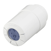
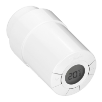
Draadloze thermostaat
Doel van regeling Kamerthermostaat voor regeling van de ruimtetemperatuur
Bereik omgevingstemperatuur, continu gebruik 0 °C tot +40 °C
Frequentie 869 MHz
Zendvermogen < 2,5 mW
Behuizing (IP-klasse) IP 21
Voedingsspanning 2 AA-alkalinebatterijen van 1,5 V
Conformiteitsverklaring op basis van de volgende richtlijnen RED, RoHS, AEEA
Beschermingsklasse Klasse III
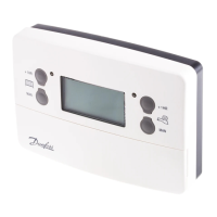
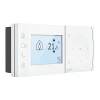
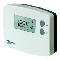
24 V bekabelde thermostaat
Doel van regeling Kamerthermostaat voor regeling van de ruimtetemperatuur
Bereik omgevingstemperatuur, continu gebruik 0 °C tot +40 °C
Behuizing (IP-klasse) IP 21
Voedingsspanning 24 V DC
Conformiteitsverklaring op basis van de volgende richtlijnen EMC, RoHS, AEEA
Elektrische veiligheid Klasse III
Externe sensor Type NTC, 47 k bij 25 °C (optioneel, 088U1110)
VIMCG30F | 088N3678 | 53
© Danfoss | FEC | 2019.02
 Loading...