The temperature switch disabling the mains supply to
VLT by a contactor
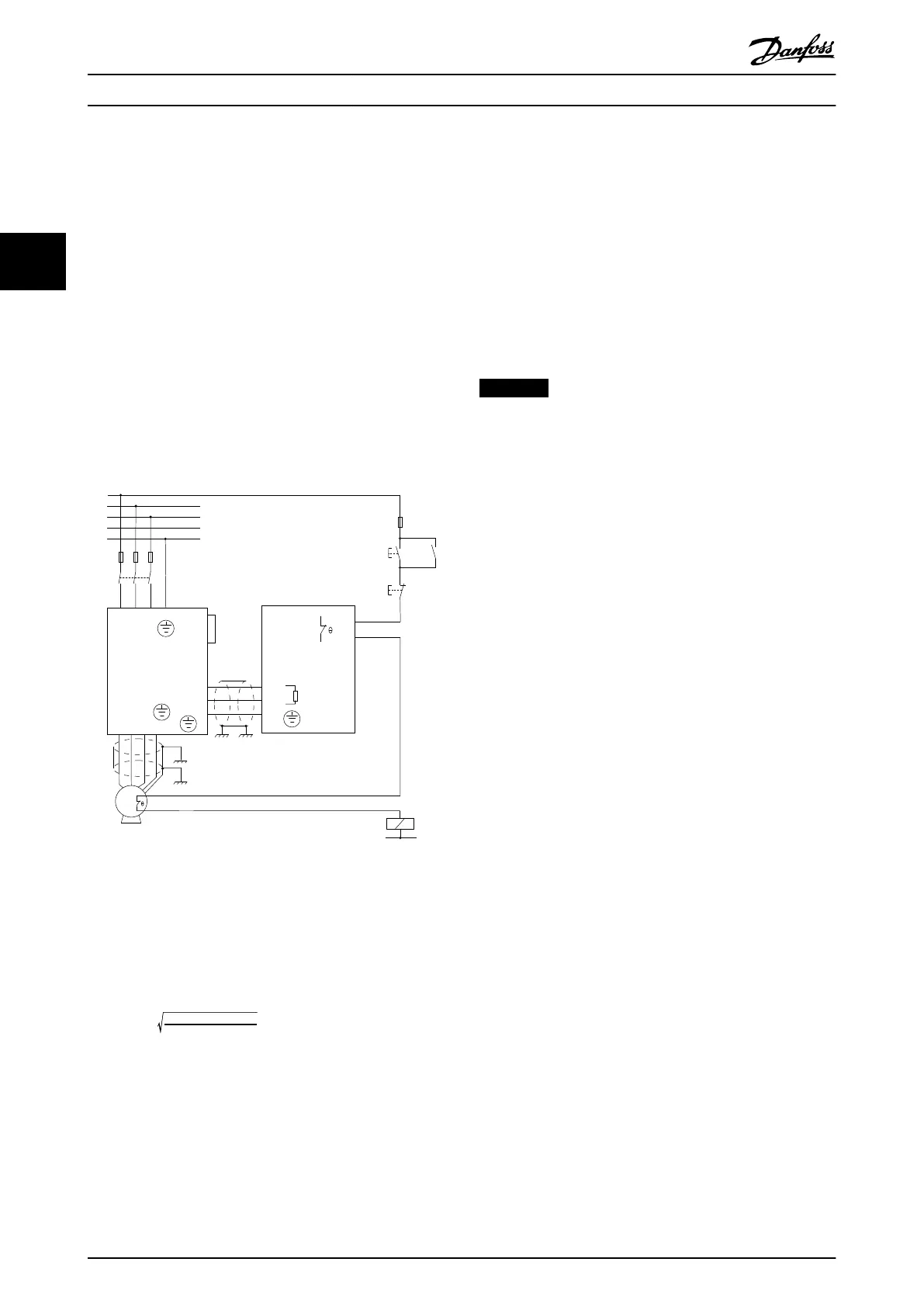
Example 2
1. Connect the brake resistor built-in thermal switch
as controlling an input contactor. In this example,
the thermal switch within the brake resistor is
connected in series with the thermal switch
within the motor.
2. Connect start and stop push buttons in series
with the thermal switches.
3. Connect to a contactor in the mains supply in
front of the frequency converter.
Thermal overheating in brake resistor or motor disables
the mains supply to the frequency converter.
Example 2
91 92 93 95
96 97 98 99
M
3~
12
27
L1 L2 L3 PE
VLT
MCE 101
Brake resistor
T1
T2
RB1
RB2
99
PE
81
R -
82R+
PE
L1
L2
L3
N
PE
F1
S1 K1
F2
S2
K1
K1
U V W PE
130BD554.11
Illustration 3.19 Temperature Switch in both Motor and Brake
Resistor disabling Mains Supply by an Input Contactor
Thermo relay disabling the brake resistor
Example 3
Calculate the brake current (I
thermo relay
) setting of the
temperature switch as follows:
I
thermo relay
=
P
brake resistor max
R
br
R
br
is the current brake resistor value calculated in
chapter 4.1.2 Calculation of Brake Resistor Resistance.
Look up the brake current setting of the thermo relay for
Danfoss brake resistors in chapter 8 Selection Guide.
3.3.2
Brake Resistor and Brake IGBT
Brake resistor power monitor
In addition, the brake power monitor function makes it
possible to read out the momentary power and the mean
power for a selected time period. The brake can also
monitor the power energising and make sure it does not
exceed a limit selected in parameter 2-12 Brake Power Limit
(kW). In 2-13 Brake Power Monitoring, select the function to
carry out when the power transmitted to the brake resistor
exceeds the limit set in parameter 2-12 Brake Power Limit
(kW).
NOTICE
Monitoring the brake power does not fulfil a safety
function. The brake resistor circuit is not ground leakage
protected.
The brake is protected against short-circuiting of the brake
resistor, and the brake transistor is monitored to ensure
that short-circuiting of the transistor is detected. Use a
relay or digital output to protect the brake resistor against
overloading in the event of a fault in the frequency
converter, see chapter 3.3.1 Overtemperature Protection.
Overvoltage control (OVC) can be selected as an alternative
brake function in parameter 2-17 Over-voltage Control. If the
DC-link voltage increases, this function is active for all
units. The function ensures that a trip can be avoided. This
is done by increasing the output frequency to limit the
voltage from the DC link. It is a useful function, e.g. if the
ramp-down time is too short since tripping of the
frequency converter is avoided. In this situation the ramp-
down time is extended.
Installation Design Guide
14 Danfoss A/S © Rev. 05/2014 All rights reserved. MG90O202
33
 Loading...


