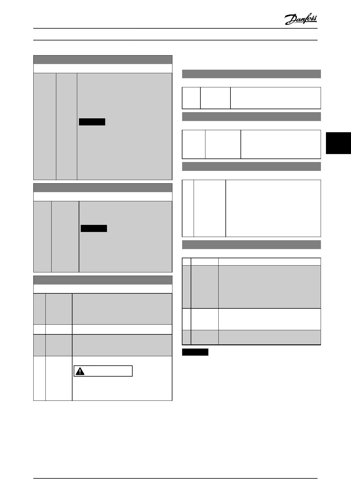
2-12 Brake Power Limit (kW)
Range: Function:
brake resistor. t
br
is the active breaking time
within the 120 s period, T
br
.
U
br
is the DC voltage where the brake
resistor is active. This depends on the unit
as follows:
T4 units: 778 V
NOTICE
If R
br
is not known or if T
br
is different
from 120 s, the practical approach is
to run the brake application, readout
16-33 Brake Energy /2 min and then
enter this + 20% in 2-12 Brake Power
Limit (kW).
2-16 AC Brake, Max current
Range: Function:
100 %* [0 - 160
%]
Enter the maximum permissible current
when using AC brake to avoid overheating
of motor windings.
NOTICE
Parameter 2-16 AC Brake, Max current
has no effect when 1-10 Motor
Construction is set to [1] PM, non-
salient SPM.
2-17 Over-voltage Control
Option: Function:
Overvoltage control (OVC) reduces the risk of
the frequency converter tripping due to an
overvoltage on the DC-link caused by
generative power from the load.
[0] * Disabled No OVC required.
[1] Enabled
(not at
stop)
Activates OVC except when using a stop signal
to stop the frequency converter.
[2] Enabled Activates OVC
WARNING
Do NOT enable OVC in hoisting
applications.
5.5
Parameters for VLT
®
2800
126 DC brake time
Range: Function:
10 sec* [0 - 60 sec.] The DC brake time is set at which
parameter 132 DC brake voltage is to be
active.
127 DC brake cut-in frequency
Range: Function:
0.00 OFF* [0.0 (OFF) -
par. 202]
Set the DC brake cut-in frequency at
which the DC brake is to be
activated in connection with a stop
command.
132 DC brake voltage
Range: Function:
0%* [0 - 100% of
max. DC
brake
voltage]
Set the DC brake voltage to be activated at
stop when the DC brake frequency set in
parameter 127 DC brake cut-in frequency is
reached, or if DC braking inverse is active via
a digital input or via serial communication.
Subsequently, the DC brake voltage is active
for the time set in parameter 126 DC brake
time.
400 Brake function
Option: Function:
[0] Off
[1] Resistor
brake
Select [1] Resistor brake if the frequency
converter has an integral brake transistor, and a
brake resistor is connected to terminals 81, 82.
A higher DC-link voltage is permitted during
braking (generated operation) when a brake
resistor is connected.
[4] AC brake
Select [4] AC brake to improve braking without
using brake resistors. Note that [4] AC brake is
not as effective as [1] Resistor brake.
[5] Load
sharing
NOTICE
Disconnected and reconnect mains voltage to activate a
change of selection.
Programming Design Guide
MG90O202 Danfoss A/S © Rev. 05/2014 All rights reserved. 25
5 5
 Loading...


