DC-link Voltage (U
dc
), FC 301/FC 302
Size [V]
Brake
active
[V DC]
High
voltage
warning
[V DC]
Over
voltage
alarm
[V DC]
FC 301 3x200-240
1)
365 405 410
FC 301 3x200-240
2)
390 405 410
FC 302 3x200-240 390 405 410
FC 301 3x380-480
1)
728 810 820
FC 301 3x380-480
2)
778 810 820
FC 302 3x380-500
3)
810 840 855
FC 302 3x380-500
4)
810 828 855
FC 302 3x525-600
3)
943 965 975
FC 302 3x525-600
4)
1099 1109 1130
FC 302 3x525-690 1099 1109 1130
Table 4.4 DC-link Voltage (U
dc
), FC 301/FC 302
1) Enclosure type A
2) Enclosure types B, C
3) Enclosure types A, B, C
4) Enclosure types D, E, F
DC-link Voltage (U
dc
), FC 360
Size [V]
Brake
active
[V DC]
High
voltage
warning
[V DC]
Over
voltage
alarm
[V DC]
FC 360 3x380-480,
0.37-22 kW
700-770
1)
800 800
FC 360 3x380-480, 30-75
kW
N/A
2)
800 800
Table 4.5 DC-link Voltage (U
dc
), FC 360
1) Adjustable with 2-14 Brake voltage reduce
2) No built-in brake option
DC-link Voltage (U
dc
), FCD 302
Size [V]
Brake
active
[V DC]
High
voltage
warning
[V DC]
Over
voltage
alarm
[V DC]
FCD 302 3x380-480 778 810 820
Table 4.6 DC-link Voltage (U
dc
), FCD 302
DC-link Voltage (U
dc
), VLT 2800
Size [V]
Brake
active
[V DC]
High
voltage
warning
[V DC]
Over
voltage
alarm
[V DC]
VLT 2800 3x200-240 385 400 410
VLT 2800 3x380-480 770 800 820
Table 4.7 DC-link Voltage (U
dc
), VLT 2800
Use the brake resistance R
rec
, to ensure that the frequency
converter is able to brake at the highest braking torque
(M
br(%)
) (e.g. 160%). The formula is written as:
R
rec
Ω =
U
dc
2
x
100
P
motor
x
M
br
%
x
η
VLT
x
η
motor
η
motor
is typically at 0.90
η
VLT
is typically at 0.98
When a higher brake resistor resistance is selected, 160%/
150%/110% braking torque cannot be obtained, and there
is a risk that the frequency converter cuts out of DC-Link
overvoltage for protection.
For braking at lower torque, for example 80% torque, it is
possible to install a brake resistor with lower power rating.
Calculate size using the formula for calculating R
rec
.
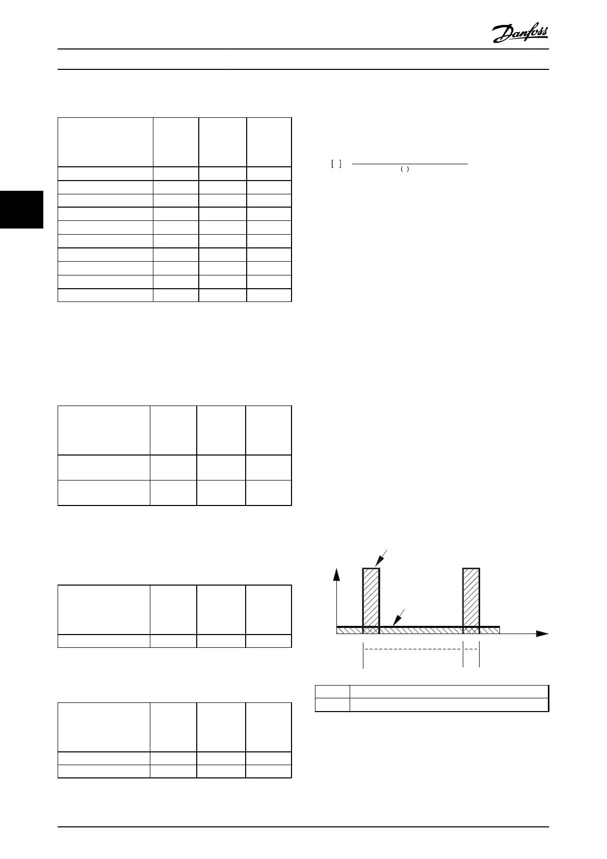
4.1.3
Calculation of Braking Power
When calculating the braking power, ensure that the brake
resistor is scaled for the average power as well as the peak
power.
•
The average power is determined by the process
period time, i.e. the length of the braking time in
relation to the process period time.
•
The peak power is determined by the braking
torque, which means that as braking progresses,
the brake resistor must be able to dissipate the
energy input.
Illustration 4.2 shows the relation between the average
power and the peak power.
peak
P
avg
T
p
T
b
t [s]
175ZA094.13
T
p
Process period time in s
T
b
Braking time in s
Illustration 4.2 Relation between Average Power and Peak
Power
System Integration Design Guide
16 Danfoss A/S © Rev. 05/2014 All rights reserved. MG90O202
44
 Loading...


