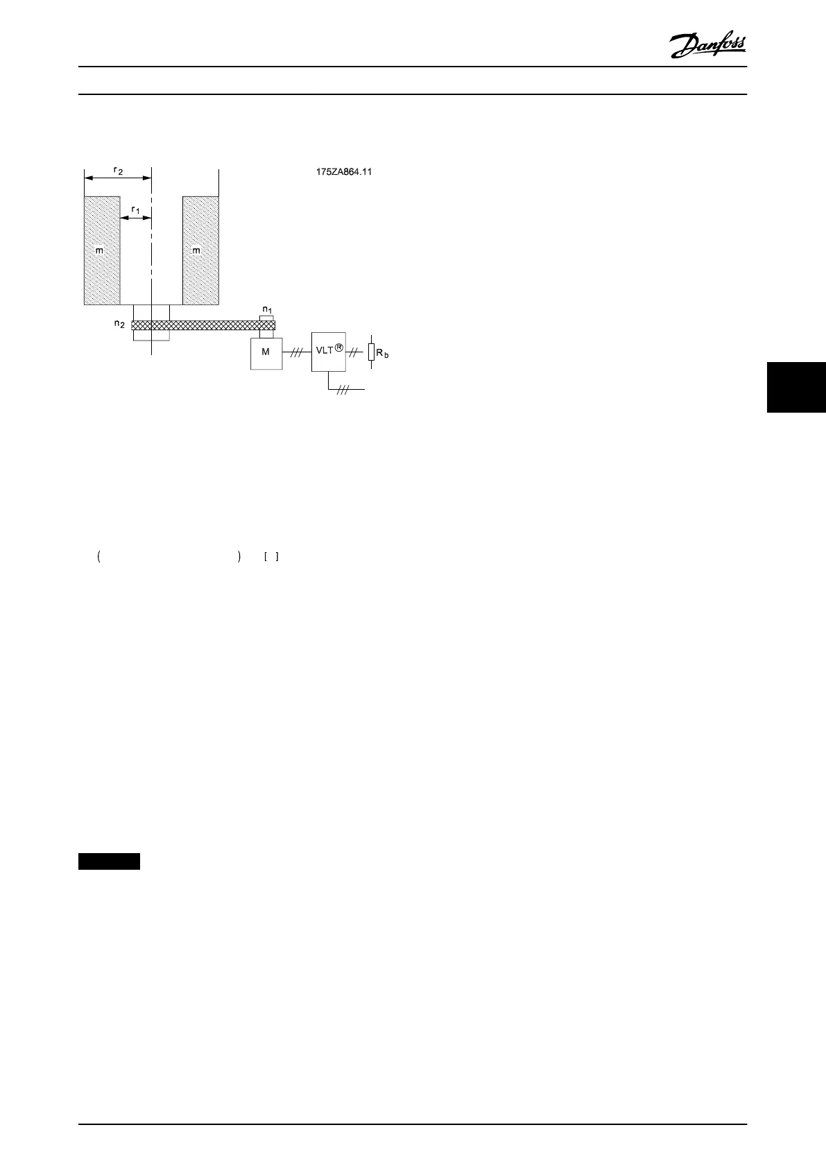
6.2 Centrifuge
Illustration 6.2 Centrifuge with Brake Resistor
Braking of a centrifuge is a typical application of brake
resistors, shown in Illustration 6.2.
The formula for energy dissipation (E
b
) to the brake resistor
is:
E
b
= 0.0055 ×
j
c
×
n
2
2
+ 0.0055 ×
j
M
×
n
1
2
× η
M
Ws
where
m = weight of the centrifuge content [kg]
j
C
= centrifuge inertia [kgm
2
] = 0.5 x m (r
1
2
+ r
2
2
)
j
M
= gear motor inertia [kgm
2
]
η
M
= gear motor efficiency
n
1
= max. motor speed [rpm]
n
2
= max. centrifuge speed [rpm]
R
b
= brake resistor
6.3
Continuous Braking
To achieve continuous braking, select a brake resistor in
which the constant braking power does not exceed the
average power P
avg
of the brake resistor.
NOTICE
Contact the Danfoss distributor for further information.
Application Examples Design Guide
MG90O202 Danfoss A/S © Rev. 05/2014 All rights reserved. 29
6 6
 Loading...


