7.1.4 DC Braking
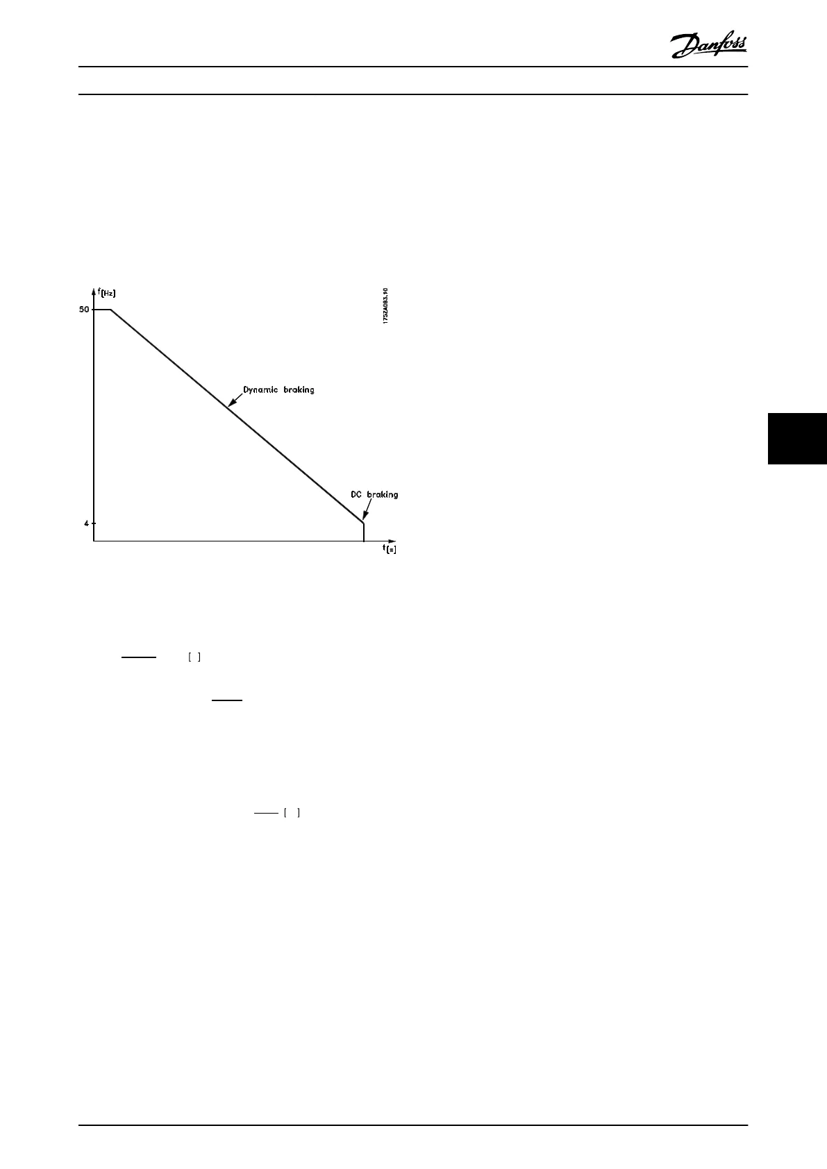
Resistor brake is useful from max. speed down to a certain
frequency. Below this frequency DC braking is to be
applied as required. The most efficient way of doing this is
to use a combination of dynamic and DC braking. See
Illustration 7.1. The parameters can be found in
chapter 5 Programming.
Illustration 7.1 Optimum Braking
How to calculate optimum DC-brake cut in frequency:
Slip
s
=
n
0
−
n
n
n
0
× 100 %
Synchronous speed
n
0
=
f
× 60
p
[1/min]
f = frequency supplied to motor
p = no. of pole pairs
n
n
= speed of the rotor
DC-brake cut in frequency = 2 ×
s
×
f
100
Hz
Special Conditions Design Guide
MG90O202 Danfoss A/S © Rev. 05/2014 All rights reserved. 31
7 7
 Loading...


