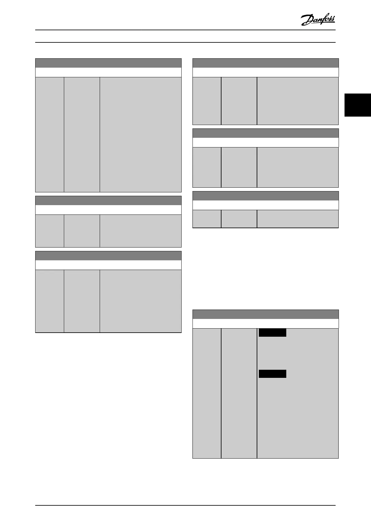
14-25 Trip Delay at Torque Limit
Range: Function:
60 s* [0 - 60 s] Enter the torque limit trip delay in
seconds. When the output torque
reaches the torque limits
(parameter 4-16 Torque Limit Motor
Mode and parameter 4-17 Torque
Limit Generator Mode), a warning is
triggered. When the torque limit
warning has been continuously
present for the period specied in
this parameter, the frequency
converter trips. Disable the trip
delay by setting the parameter to
60 s=OFF. Thermal frequency
converter monitoring remains
active.
14-26 Trip Delay at Inverter Fault
Range: Function:
Size
related*
[0 - 35 s] When the frequency converter
detects an overvoltage in the set
time, trip is eected after the set
time.
14-29 Service Code
Range: Function:
0* [-2147483647
-
2147483647 ]
Enter code 5000 to restore the 8
digit order number in
parameter 15-46 Frequency Converter
Ordering No after a power card
exchange. The number should
match the ordering number on the
nameplate of the frequency
converter.
3.14.3 14-3* Current Limit Control
The frequency converter features an integral current limit
controller which is activated when the motor current, and
thus the torque, is higher than the torque limits set in
parameter 4-16 Torque Limit Motor Mode and
parameter 4-17 Torque Limit Generator Mode.
When the current limit is reached during motor operation
or regenerative operation, the frequency converter tries to
reduce torque below the preset torque limits as quickly as
possible without losing control of the motor.
While the current control is active, the frequency converter
can only be stopped by setting a digital input to [2] Coast
inverse or [3] Coast and reset inv. Any signal on terminals
18–33 are not active until the frequency converter is no
longer near the current limit.
By using a digital input set to [2] Coast inverse or [3] Coast
and reset inv., the motor does not use the ramp down
time, since the frequency converter is coasted.
14-30 Current Lim Ctrl, Proportional Gain
Range: Function:
100 %* [0 - 500 %] Enter the proportional gain value
for the current limit controller.
Selection of a high value makes the
controller react faster. Too high a
setting leads to controller
instability.
14-31 Current Lim Ctrl, Integration Time
Range: Function:
Size
related*
[0.002 - 2 s] Controls the current limit control
integration time. Setting it to a
lower value makes it react faster. A
setting too low leads to controller
instability.
14-32 Current Lim Ctrl, Filter Time
Range: Function:
Size
related*
[1 - 100 ms] Sets a time constant for the current
limit controller low-pass lter.
3.14.4 14-4* Energy Optimising
Parameters for adjusting the energy optimization level in
both variable torque (VT) and automatic energy optimi-
zation (AEO) mode.
Automatic energy optimization is only active if
parameter 1-03 Torque Characteristics, is set for either [2]
Auto Energy Optim. Compressor or [3] Auto Energy Optim. VT.
14-40 VT Level
Range: Function:
66 %* [40 - 90 %]
NOTICE
This parameter cannot be
adjusted while the motor is
running.
NOTICE
This parameter is not active
when parameter 1-10 Motor
Construction is set to [1] PM
non-salient SPM.
Enter the level of motor magneti-
zation at low speed. Selection of a
low value reduces energy loss in
the motor but also reduces load
capability.
Parameter Descriptions Programming Guide
M0010001 Danfoss A/S © 10/2019 All rights reserved. 151
3 3
 Loading...


