14-41 AEO Minimum Magnetisation
Range: Function:
Size
related*
[ 40 - 200 %]
NOTICE
This parameter is not active
when parameter 1-10 Motor
Construction is set to [1] PM
non-salient SPM.
Enter the minimum allowable
magnetization for AEO. Selection of
a low value reduces energy loss in
the motor but can also reduce
resistance to sudden load changes.
14-42 Minimum AEO Frequency
Range: Function:
Size
related*
[5 - 255 Hz]
NOTICE
This parameter is not active
when parameter 1-10 Motor
Construction is set to [1] PM
non-salient SPM.
Enter the minimum frequency at
which the automatic energy optimi-
zation (AEO) is to be active.
14-43 Motor Cosphi
Range: Function:
Size
related*
[0.40 - 0.95 ] The Cos(phi) setpoint is automat-
ically set for optimum AEO
performance during AMA. This
parameter should normally not be
altered. However, in some situations
it may be necessary to enter a new
value to ne-tune.
3.14.5 14-5* Environment
NOTICE
Perform a power cycle after changing any of the
parameters in parameter group 14-5* Environment.
These parameters help the frequency converter to operate
under special environmental conditions.
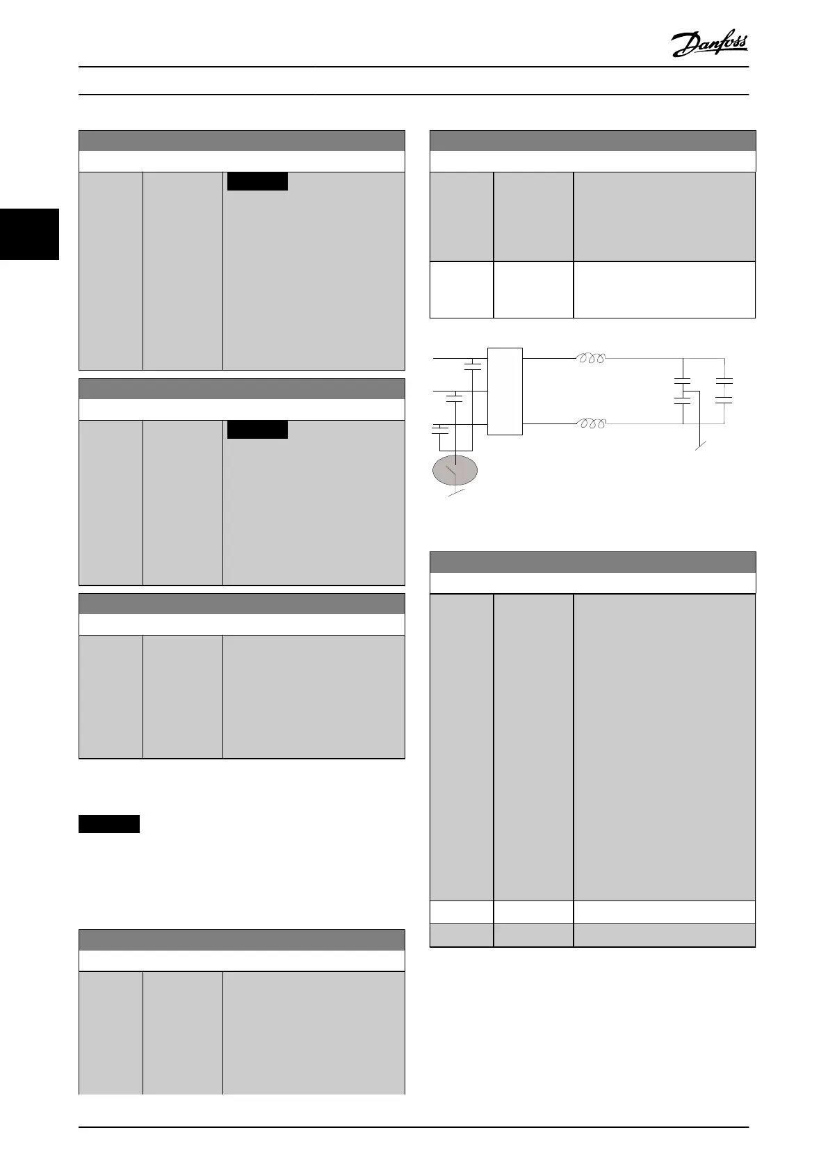
14-50 RFI Filter
Option: Function:
[0] O Select [0] O if the frequency
converter is fed by an isolated
mains source (IT mains).
If a lter is used, select [0] O
during charging to prevent a high
leakage current making the RCD
switch.
14-50 RFI Filter
Option: Function:
In this mode, the internal RFI lter
capacitors between chassis and the
mains RFI lter circuit are cut out to
reduce the ground capacity
currents.
[1] * On Select [1] On to ensure that the
frequency converter complies with
EMC standards.
Illustration 3.49 RFI Filter
Option: Function:
The rectied AC-DC voltage in the
frequency converter's DC link is
associated with voltage ripples.
These ripples can increase in
magnitude with increased load.
These ripples are undesirable
because they can generate current
and torque ripples. A compensation
method is used to reduce these
voltage ripples in the DC link. In
general, DC-link compensation is
recommended for most
applications, but pay attention
when operating in eld weakening
as it can generate speed oscillations
at the motor shaft. In eld
weakening, turn o DC-link
compensation.
[0] O Disables DC-link compensation.
[1] On Enables DC-link compensation.
Parameter Descriptions
VLT
®
HVAC Drive FC 102
152 Danfoss A/S © 10/2019 All rights reserved. M0010001
33
 Loading...


