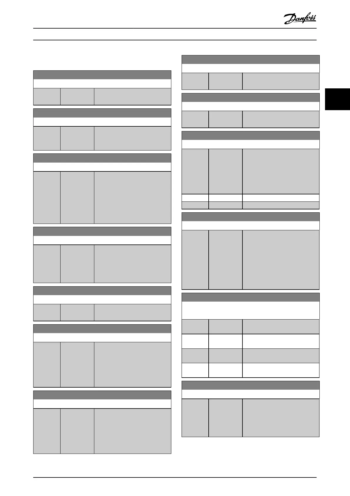
3.16.3 16-3* Drive Status
16-30 DC Link Voltage
Range: Function:
0 V* [0 - 10000 V] View a measured value. The value is
ltered with a 30 ms time constant.
16-32 Brake Energy /s
Range: Function:
0 kW* [0 - 10000
kW]
View the brake power transmitted
to an external brake resistor, stated
as an instant value.
16-33 Brake Energy Average
Range: Function:
0 kW* [0 - 10000
kW]
View the brake power transmitted
to an external brake resistor. The
mean power is calculated on an
average level based on the selected
time period within
parameter 2-13 Brake Power
Monitoring.
16-34 Heatsink Temp.
Range: Function:
0 °C* [0 - 255 °C] View the frequency converter heat
sink temperature. The cutout limit is
90 ±5 °C (194 ±9 °F), and the
motor cuts back in at 60 ±5 °C (140
±9 °F).
16-35 Inverter Thermal
Range: Function:
0 %* [0 - 100 %] View the thermal load on the
inverter. The cutout limit is 100%.
16-36 Inv. Nom. Current
Range: Function:
Size
related*
[0.01 - 10000
A]
View the inverter nominal current,
which should match the nameplate
data on the connected motor. The
data is used for calculation of
torque, motor overload protection,
and so on.
16-37 Inv. Max. Current
Range: Function:
Size
related*
[0.01 - 10000
A]
View the inverter maximum current,
which should match the nameplate
data on the connected motor. The
data is used for calculation of
torque, motor overload protection,
and so on.
16-38 SL Controller State
Range: Function:
0* [0 - 100 ] View the state of the event under
execution by the SL controller.
16-39 Control Card Temp.
Range: Function:
0 °C* [0 - 100 °C] View the temperature on the
control card, stated in °C.
16-40 Logging Buer Full
Option: Function:
View whether the logging buer is
full (see parameter group 15-1* Data
Log Settings). The logging buer is
never full when
parameter 15-13 Logging Mode is set
to [0] Log always.
[0] * No
[1] Yes
16-42 Service Log Counter
Range: Function:
0* [ 0 - 24 ] Shows the number of service logs
stored in the ServiceLog le. If the
ServiceLog le is full, clear the
logged data by selecting option [5]
Clear service logs in
parameter 14-22 Operation Mode.
The logged data is deleted on the
next power-up.
16-43 Timed Actions Status
Select the timed actions view.
Option: Function:
[0] * Timed Actions
Auto
[1] Timed Actions
Disabled
[2] Constant On
Actions
[3] Constant O
Actions
16-45 Motor Phase U Current
Range: Function:
0 A* [0 - 10000 A] Shows the motor phase U
RMS
current. Facilitates monitoring of
imbalance in the motor currents,
detection of weak motor cables or
imbalance in motor windings.
Parameter Descriptions Programming Guide
M0010001 Danfoss A/S © 10/2019 All rights reserved. 165
3 3
 Loading...


