16-56 Feedback 3 [Unit]
Range: Function:
0
ProcessCtrl
Unit*
[-999999.999
- 999999.999
ProcessCtrlUnit
]
View value of feedback 3, see
parameter group 20-0* Feedback.
The value is limited by settings in
parameter 20-13 Minimum Reference/
Feedb. and
parameter 20-14 Maximum
Reference/Feedb.. Units as set in
parameter 20-12 Reference/Feedback
Unit.
16-58 PID Output [%]
Range: Function:
0 %* [0 - 100 %] This parameter returns the
frequency converter closed-loop PID
controller output value in percent.
3.16.5 16-6* Inputs and Outputs
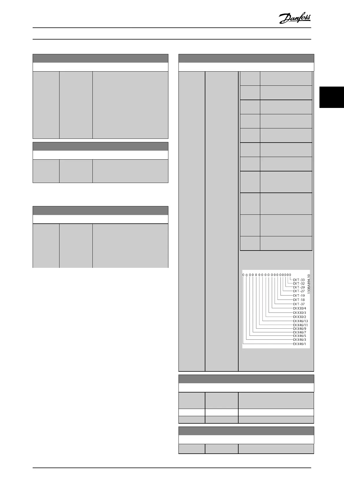
16-60 Digital Input
Range: Function:
0* [ 0 - 65535 ] View the signal states from the
active digital inputs. Example: Input
18 corresponds to bit number 5, 0
= no signal, 1 = connected signal.
Bit 6 works in the opposite way, on
= 0, o = 1 (Safe Torque O input).
16-60 Digital Input
Range: Function:
Bit 0 Digital input terminal
33.
Bit 1 Digital input terminal
32.
Bit 2 Digital input terminal
29.
Bit 3 Digital input terminal
27.
Bit 4 Digital input terminal
19.
Bit 5 Digital input terminal
18.
Bit 6 Digital input terminal
37.
Bit 7
Digital input VLT
®
General Purpose I/O
MCB 101 terminal X30/4.
Bit 8
Digital input VLT
®
General Purpose I/O
MCB 101 terminal X30/3.
Bit 9
Digital input VLT
®
General Purpose I/O
MCB 101 terminal X30/2.
Bit 10–
63
Reserved for future
terminals.
Table 3.22 Active Digital Inputs
Illustration 3.51 Relay Settings
16-61 Terminal 53 Switch Setting
Option: Function:
View the setting of input terminal
53.
[0] * Current
[1] Voltage
16-62 Analog Input 53
Range: Function:
0* [-20 - 20 ] View the actual value at input 53.
Parameter Descriptions Programming Guide
M0010001 Danfoss A/S © 10/2019 All rights reserved. 167
3 3
 Loading...


