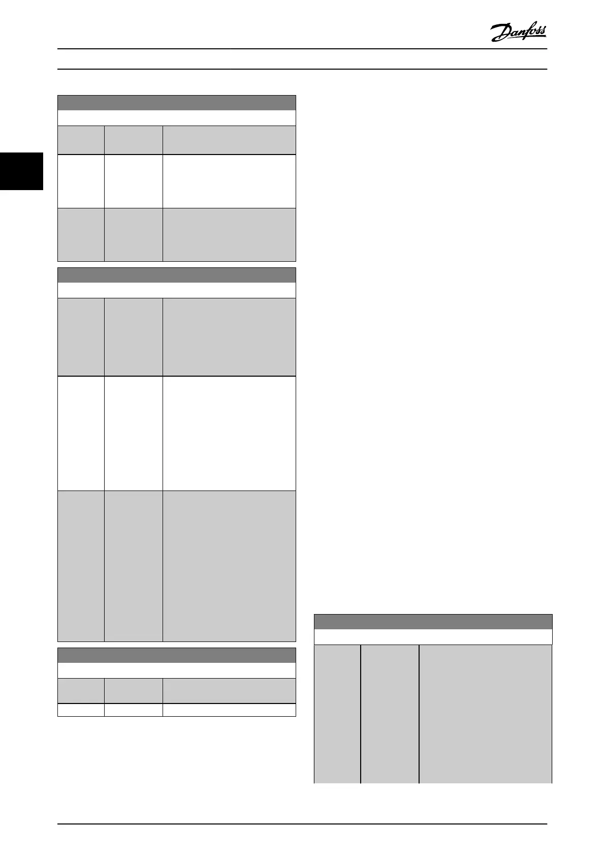
0-03 Regional Settings
Option: Function:
The settings not used are made
invisible.
[0] International Sets parameter 1-20 Motor Power
[kW] units to [kW] and the default
value of parameter 1-23 Motor
Frequency to 50 Hz.
[1] North America Sets parameter 1-21 Motor Power
[HP] units to [hp] and the default
value of parameter 1-23 Motor
Frequency to 60 Hz.
0-04 Operating State at Power-up
Option: Function:
Select the operating mode after
reconnection of the frequency
converter to mains voltage after
power-down when operating in
hand-on (local) mode and in auto
mode.
[0] * Resume Resumes operation of the
frequency converter maintaining
the same local reference and the
same start/stop condition. The
start/stop condition is applied by
[Hand On]/[O] on the LCP or local
start via a digital input as before
the frequency converter was
powered down.
[1] Forced stop,
ref=old
Stops the frequency converter, but
at the same time retains the local
speed reference before power-down
in the memory. After mains voltage
is reconnected and after receiving a
start command (pressing [Hand On]
or local start command via a digital
input), the frequency converter
restarts and operates at the
retained speed reference. Press
[Auto On] button on the LCP to
restart in auto mode.
0-05 Local Mode Unit
Option: Function:
[0] * As Motor
Speed Unit
[1] %
3.2.2 0-1* Set-up Operations
Dene and control the individual parameter set-ups.
The frequency converter has 4 parameter set-ups that can
be programmed independently of each other. This makes
the frequency converter very exible and able to meet the
requirements of many dierent HVAC system control
schemes, often saving the cost of external control
equipment. For example, these can be used to program
the frequency converter to operate according to 1 control
scheme in 1 set-up (for example daytime operation) and
another control scheme in another set-up (for example
night set back). Alternatively, they can be used by an AHU
or packaged unit OEM to identically program all their
factory tted frequency converters for dierent equipment
models within a range to have the same parameters, and
then during production/commissioning simply select a
specic set-up depending on which model within that
range the frequency converter is installed on.
The active set-up (that is the set-up in which the frequency
converter is currently operating) can be selected in
parameter 0-10 Active Set-up and is displayed in the LCP.
Using [9] Multi set-up it is possible to switch between set-
ups with the frequency converter running or stopped, via
digital input or serial communication commands (for
example for night set back). If it is necessary to change
setups while running, ensure that parameter 0-12 This Set-
up Linked to is programmed as required. For most HVAC
applications it is not necessary to program
parameter 0-12 This Set-up Linked to even if change of set
up while running is required, but for very complex
applications, using the full
exibility of the multiple set-
ups, it may be required. Using parameter 0-11 Programming
Set-up it is possible to edit parameters within any of the
set-ups while continuing the frequency converter
operation in its active set-up which can be a dierent set-
up to the one being edited. Using parameter 0-51 Set-up
Copy it is possible to copy parameter settings between the
set-ups to enable quicker commissioning if similar
parameter settings are required in dierent set-ups.
If a set-up is changed via a eldbus, it takes up to 5 s
before the new values are reected via the eldbus.
0-10 Active Set-up
Option: Function:
Select the set-up in which the
frequency converter is to operate.
Use parameter 0-51 Set-up Copy to
copy a set-up to 1 or all other set-
ups. To avoid conicting settings of
the same parameter within 2
dierent set-ups, link the set-ups
using parameter 0-12 This Set-up
Linked to. Stop the frequency
converter before switching between
set-ups where parameters marked
Parameter Descriptions
VLT
®
HVAC Drive FC 102
28 Danfoss A/S © 10/2019 All rights reserved. M0010001
33