3-82 Starting Ramp Up Time
Range: Function:
Size
related*
[0.01 - 3600
s]
The ramp-up time is the
acceleration time from 0 RPM to
the nominal motor speed set in
parameter 3-82 Starting Ramp Up
Time when [0] Compressor Torque is
active in parameter 1-03 Torque
Characteristics.
3.5.6 3-9* Digital Pot.Meter
Use the digital potentiometer function to increase or
decrease the actual reference by adjusting the set-up of
the digital inputs using the functions increase, decrease, or
clear. To activate the function, at least 1 digital input must
be set to increase or decrease.
3-90 Step Size
Range: Function:
0.10 %* [0.01 -
200 %]
Enter the increment size required
for increase/decrease as a
percentage of the synchronous
motor speed, n
s
. If increase/
decrease is activated, the resulting
reference is increased or decreased
by the value set in this parameter.
3-91 Ramp Time
Range: Function:
1 s [0 - 3600 s] Enter the ramp time, that is, the
time for adjusting the reference 0–
100% of the specied digital
potentiometer function (increase,
decrease, or clear).
If increase/decrease is activated for
longer than the ramp delay period
specied in parameter 3-95 Ramp
Delay, the actual reference is
ramped up/down according to this
ramp time. The ramp time is
dened as the time spent to adjust
the reference by the step size
specied in parameter 3-90 Step
Size.
3-92 Power Restore
Option: Function:
[0] * O Resets the digital potentiometer
reference to 0% after power-up.
[1] On Restores the most recent digital
potentiometer reference at power-
up.
3-93 Maximum Limit
Range: Function:
100 %* [-200 -
200 %]
Set the maximum allowed value for
the resulting reference. This is
recommended if the digital potenti-
ometer is used for ne-tuning of
the resulting reference.
3-94 Minimum Limit
Range: Function:
0 %* [-200 -
200 %]
Set the minimum allowed value for
the resulting reference. This is
recommended if the digital potenti-
ometer is used for ne-tuning of
the resulting reference.
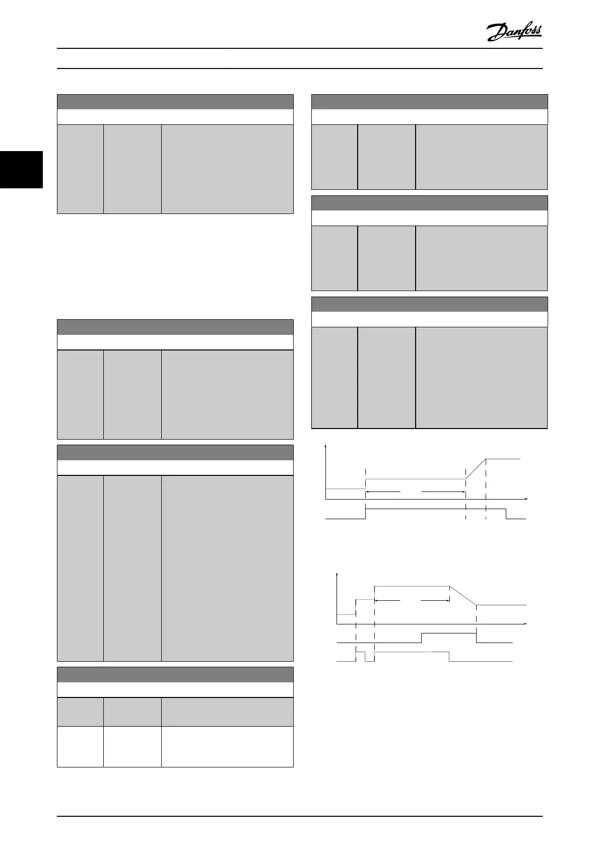
3-95 Ramp Delay
Range: Function:
Size
related*
[ 0.000 -
0.000 ]
Enter the delay required from
activation of the digital potenti-
ometer function until the frequency
converter starts to ramp the
reference. With a delay of 0 ms, the
reference starts to ramp when
increase/decrease is activated. See
also parameter 3-91 Ramp Time.
Speed
Time (s)
Inc
130BA158.11
P 3-95
Illustration 3.23 Ramp Delay Case 1
Speed
Time (s)
Dec
Inc
130BA159.11
P 3-95
Illustration 3.24 Ramp Delay Case 2
Parameter Descriptions
VLT
®
HVAC Drive FC 102
80 Danfoss A/S © 10/2019 All rights reserved. M0010001
33
 Loading...


