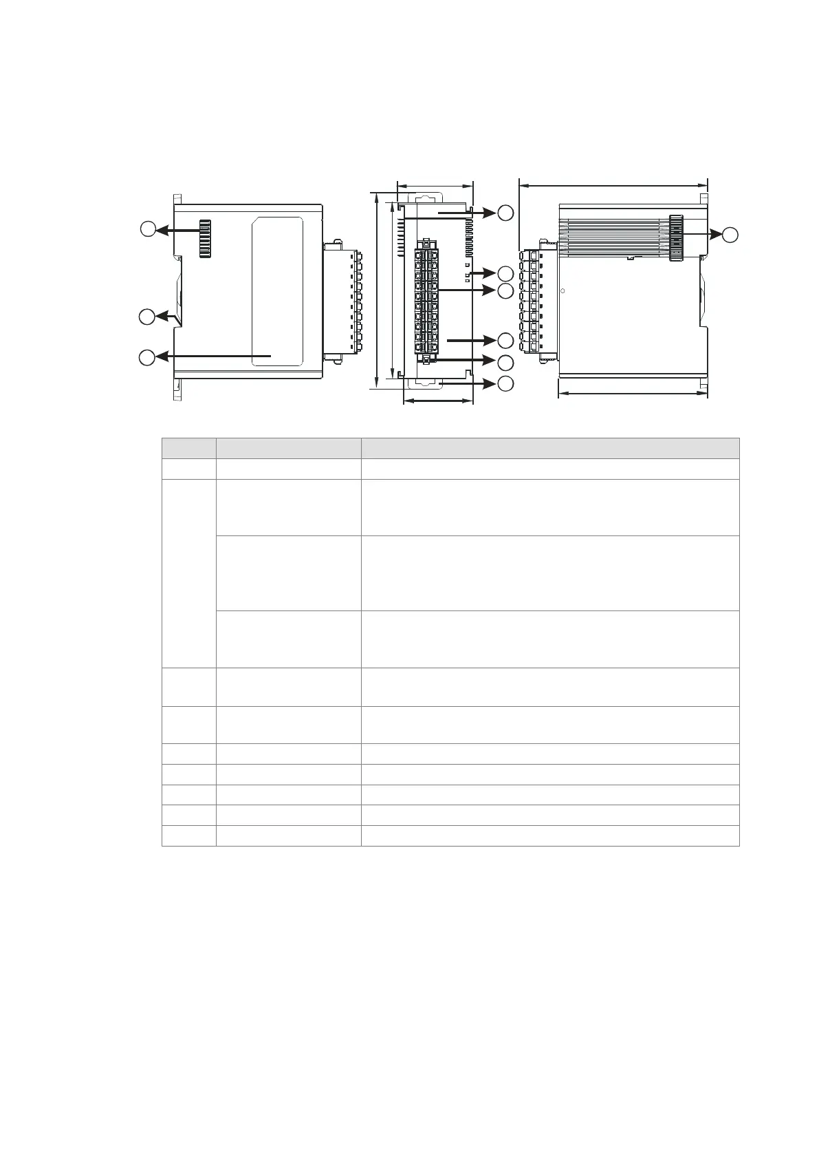
2.9.2 Load Cell Module Profiles
AS02LC-A
38.2
35
88
98.3
1
4
5
2
3
6
7
8
9
95
75
7
Unit: mm
1 Model name Model name of the module
2
POWER LED indicator
Indicates the status of the power supply
ON: the power is on
ERROR LED indicator
Error status of the module
ON: a serious error occurs in the module.
OFF: the module is normal.
Blinking: a minor error occurs in the module.
Analog to digital
conversion indicator
Indicates the analog to digital conversion status
Blinking: conversion is taking place
OFF: stop conversion
3
Removable terminal
block
The inputs are connected to sensors.
The outputs are connected to loads to be driven.
4
Arrangement of the
input/output terminals
Arrangement of the terminals
5 Terminal block clip Removal of the terminal block
Secures the module onto the DIN rail
Send Quote Requests to info@automatedpt.com
Call +1(800)985-6929 To Order or Order Online At Deltaacdrives.com
Send Quote Requests to info@automatedpt.com
Call +1(800)985-6929 To Order or Order Online At Deltaacdrives.com
 Loading...