4.9.6 Wiring AS02ADH-A
Precautions
To ensure the analog-to-digital module functions well and reliably, the external wiring must prevent noise.
Before you install the cables, follow the precautions below.
(1) To prevent a surge and induction, the AC cable and the input signal cables that are connected to the
module must be separate cables.
(2) Do not install the cable near a main circuit, a high-voltage cable, or a cable connected to a load that is not
a PLC. In addition, the cable must not be bound to a main circuit, a high-voltage cable, or a cable
connected to a load which is not a PLC.
(3) Ground shielded cables and hermetically sealed cables separately.
(4) Terminals with insulation sleeves cannot be arranged as a terminal block, so you should cover the
terminals with insulation tubes.
(5) Use single-core cables or twin-core cables in a diameter of 24 AWG–22 AWG with pin-type connectors
smaller than 1 mm. Use only copper conducting wires that can resist temperatures above 60° C-75° C.
(6) Notes on two-wire, three-wire, and four-wire connections:
Two-wire connection/three-wire connection (passive transducer): connect the transducer and the
analog input module to the same power circuit.
Four-wire connection (active transducer): the transducer uses an independent power supply so
do not connect it to the same power circuit as the analog input module.
(7) Note: use cables with the same length (less than 200 m) and use wire resistance of less than 20 ohm.
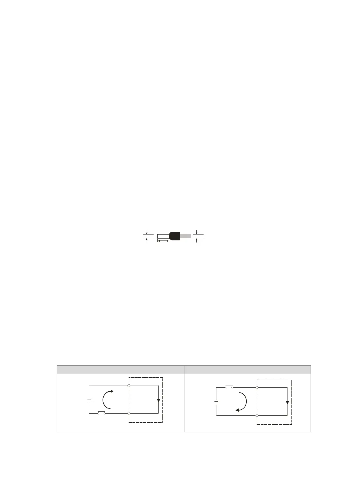
4.9.6.1 Digital Input Wiring
Send Quote Requests to info@automatedpt.com
Call +1(800)985-6929 To Order or Order Online At Deltaacdrives.com
Send Quote Requests to info@automatedpt.com
Call +1(800)985-6929 To Order or Order Online At Deltaacdrives.com
 Loading...