12.4.7
Error Codes and LED Indicators for Module AS00SCM as a
Communication Module
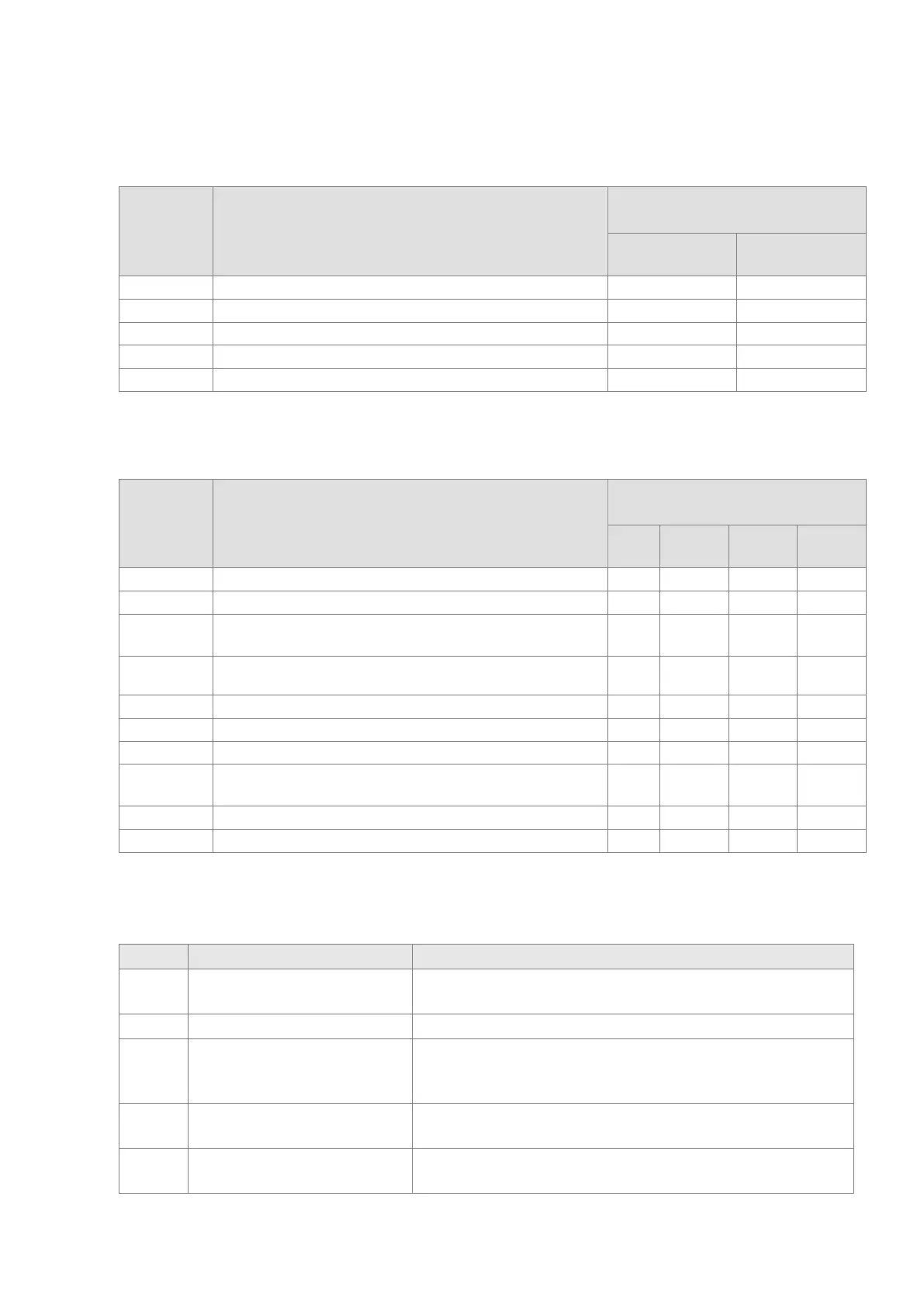
Error Code Description
ERROR LED indicator status
ON Blinking
The setting of the function card is incorrect.
16#1803 Communication timeout
16#1804 The setting of the UD Link is incorrect.
12.4.8
Error Codes and LED Indicators for Module AS00SCM as a
Remote Module
Error Code Description
ERROR LED indicator status
ON Blinking
Blinking
Blinking
The setting of the function card is incorrect.
16#1303
24 VDC power supply is not sufficient and then is recovered
from a low-voltage less than 10ms situation.
V
16#1304
More than eight remote modules on
the right side of the CPU module.
V
16#1500
Remote module communication timeout
16#1503
Extension module communication timeout
16#1505
The actual placement of the extension modules is NOT the
same as it is set.
V
16#1506
Remote module had been stopped. V
16#1604
Extension module communication timeout
12.4.9
Error Codes and LED Indicators for Module AS01DNET
(Master/Slave Mode)
Code Explanation Correction
0~63
Node address of AS01DNET-A
--
80 AS01DNET-A is in STOP status. Turn the PLC to RUN and start I/O data exchange
F0
The node ID of AS01DNET is the
same as that of other node or
exceeds the allowed range.
1. Ensure that the node address of AS01DNET is unique.
2. Re-power AS01DNET.
F1 No configured slave in Scan List.
Configure the scan list and then download the configuration to
AS01DNET.
F2
Too low voltage of the work
power
Check if the power supply for AS01DNET and the PLC is normal.
Send Quote Requests to info@automatedpt.com
Call +1(800)985-6929 To Order or Order Online At Deltaacdrives.com
Send Quote Requests to info@automatedpt.com
Call +1(800)985-6929 To Order or Order Online At Deltaacdrives.com
 Loading...