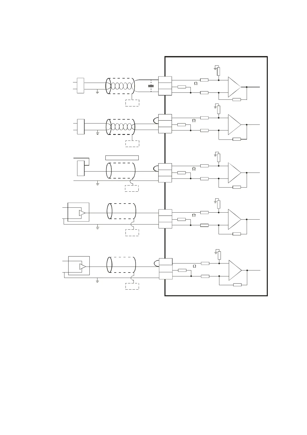
4.14.4 Wiring AS-F2AD
0V~+10V
V1+
I1+
COM
CHX
V1 +
I1+
*3
*2
CH 1
1 M
CH1
AG
1M
1M
AG
1M
25 0
250
FE
*4
+
-
4mA~ +20m A
V2 +
I2+
*2
CH2
1M
AG
1M
250
*4
FE
+
-
+
-
+24V
0V
V 2+
I2+
CH2
1M
AG
1M
250
+24V
0V
4mA~ +20m A
CH 1
1M
AG
1M
250
4mA~ +20m A
+2 4V
+
-
V1+
I1+
*2
0V~+10V
+24V
+
-
*4
FE
*4
FE
*4
FE
0V
+24 V
0V
0V
*5
CHX
*5
CH X
*5
CHX
*5
CH X
*5
COM
COM
COM
COM
Shi el de d c able 1*
Shi el de d c able 1*
4-wi re voltage input
4-wi re curren t in p ut
2 -wir e current inp u t
Shi el de d c able 1*
Shi el de d c able 1*
3 -wir e curre nt inpu t
3 -wir e voltag e inpu t
*1. Use shielded cables to isolate the analog input signal cable from other power cables.
*2. If the module is connected to a current signal, the terminals Vn and In+ (n=1–2) must be short-circuited.
*3. If noise in the input voltage results in noise interference in the wiring, connect the module to a capacitor with
a capacitance between 0.1–0.47 μF with a working voltage of 25 V.
*4. Connect FE of the shielded cable to ground.
*5. CHX: Every channel can work with the input wiring shown above.
Send Quote Requests to info@automatedpt.com
Call +1(800)985-6929 To Order or Order Online At Deltaacdrives.com
Send Quote Requests to info@automatedpt.com
Call +1(800)985-6929 To Order or Order Online At Deltaacdrives.com
 Loading...