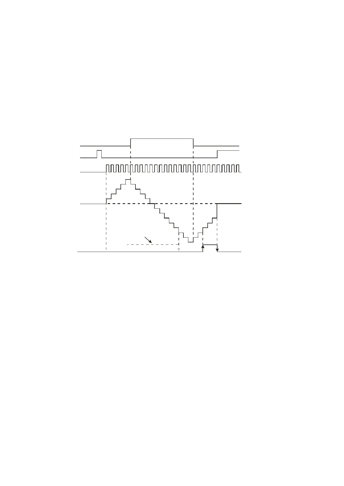
1. X10.0 drives SM621 to determine counting direction (up/down) of HC0.
2. When X11.0 goes from OFF to ON, RST instruction executes, the PV in HC0 is cleared to 0, and its
contact is OFF.
3. When X12.0 goes from OFF to ON, PV of HC0 counts up (plus 1) or down (minus 1).
4. When PV in HC0 changes from -6 to -5, the contact HC0 goes from OFF to ON. When PV in HC0
changes from -5 to -6, the contact HC0 goes from ON to OFF.
X10.0
X11.0
X12.0
When the output c ontact w as O N
Y0.0,
HC0
Contacts
HC0
( )PV
Accumulatively
increasing
Progressively
decreasing
0
1
2
3
4
5
4
3
2
1
0
-1
-2
-3
-4
-5
-6
-7
-8
0
-7
-6
-5
-4
-3
Accumulatively
increasing
5.2.12 Data Registers (D)
The data register stores 16-bit data. The highest bit represents either a positive sign or a negative sign, and
the values that you can store in the data registers are between -32,768 to +32,767. Two 16-bit registers can
be combined into a 32-bit register, that is, (D+1, D) in which the register whose number is smaller represents
the lower 16 bits. The highest bit represents either a positive sign or a negative sign, and the values that you
can store in the data registers are between -2,147,483,648 to +2,147,483,647. Four 16-bit registers can be
combined into a 64-bit register; that is, (D+3, D+2, D+1, D) in which the register whose number is smaller
represents the lower 16 bits. The highest bit represents either a positive sign or a negative sign, and the
values which can be stored in the data registers are between -9,223,372,036,854,776 to
+9,223,372,036,854,775,807. You can also use the data registers to refresh the values in the control registers
in the modules other than digital I/O modules. Refer to the ISPSoft / DIADesigner User Manual for more
information about refreshing the values in the control registers.
Send Quote Requests to info@automatedpt.com
Call +1(800)985-6929 To Order or Order Online At Deltaacdrives.com
Send Quote Requests to info@automatedpt.com
Call +1(800)985-6929 To Order or Order Online At Deltaacdrives.com
 Loading...