2.10 Extension Card Specifications
2.10.1 General Specifications
AS-F2AD
Two DC analog signal input channels:
Item Voltage Input Current Input
Rated Input Range
0 V - 10 V 4 mA - 20 mA
Resolution
12-bit 11-bit
Digital Conversion
0 - 4000 0 - 2000
Hardware Input
1
0V ~ +10.24V
4mA ~ 20.37mA (FW V1.00)
3.63mA ~ 20.37mA (FW V1.20 or later)
Digital Conversion
2
0 ~ 4095
0 ~ 2047 (FW V1.00)
- 48 ~ 2047(FW V1.20 or later)
Error Rate
room temperature: ±0.5% ; full temperature range: ±1.0%
Isolation
The isolation between digital and analog is 500 VAC; no isolation between channels.
Input Impedance
2 MΩ 250 Ω
Conversion Time*
3
3 ms / CH
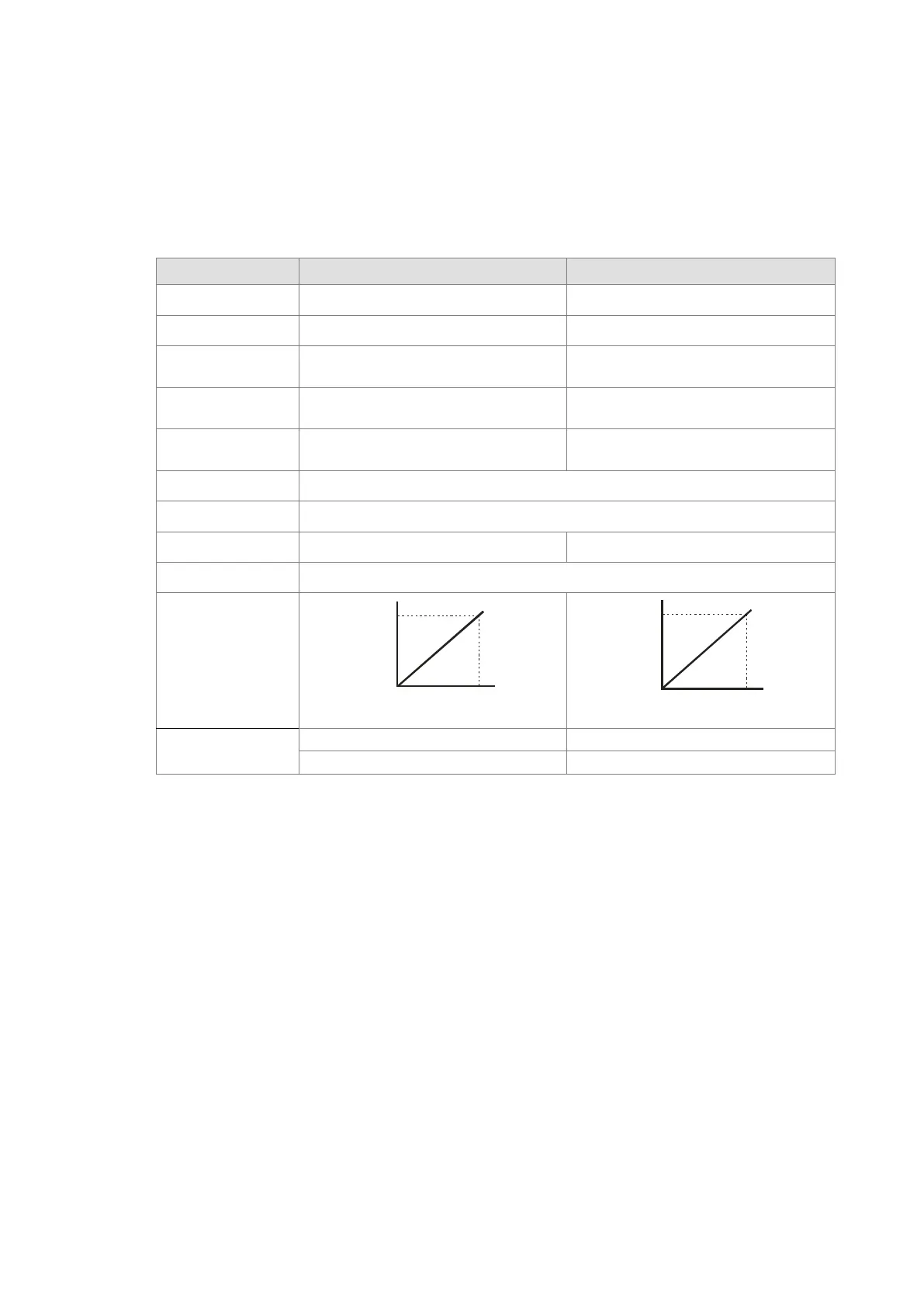
Characteristic
Curve
10V
4000
0
Voltage input
Digital Value Output
Current input
Digital Value Output
20mA
2000
4
Digital Value
Output*
4
*1: The input signal should NOT exceed the limit. If exceeding the limit, damage may occur.
*2: If the input signal exceeds the hardware input limit, the module only shows the maximum value. If the input
signal is below the lower limit, it only shows the minimum value. If the input signal exceeds the hardware input
limit, it also exceeds the digital conversion limit and a conversion limit error appears. For example in the
current input mode (4 mA to 20 mA), when the input signal is 0 mA, exceeding the hardware lower limit, it also
exceeds the conversion lower limit. The module uses the lower limit value (-48) as the input signal. If a
disconnected analysis is required, you can check if the digital conversion value is -48.
*3: The conversion time is the time for each channel to convert signals to hardware input signals. If you need
to calculate a complete conversion time, you need to add the PLC scan time.
*4: Use the program to read the values in SR to obtain the corresponding A/D conversion value for the
channel.
*5: Refer to section 2.2.16 SM/SR notes for more information on descriptions of SM27/SR27 analog input
error codes.
Send Quote Requests to info@automatedpt.com
Call +1(800)985-6929 To Order or Order Online At Deltaacdrives.com
Send Quote Requests to info@automatedpt.com
Call +1(800)985-6929 To Order or Order Online At Deltaacdrives.com
 Loading...