Chapter 8 Option CardsC2000
8-16
8-7 EMC-PG01L / EMC-PG02L -- PG card (Line driver)
8-7-1 Terminal description
Set by Pr.10-00–10-02
, Pr.10-16–10-18
Terminals Descriptions
PG1
VP
Output voltage for power: +5V/+12V5% (use FSW3 to switch
+5V/+12V)
Max. output current: 200mA
DCM
Common for power and signal
A1, /A1, B1,
/B1, Z1, /Z1
Encoder input signal (Line Driver or Open Collector)
Open Collector input voltage: +5–+24V (Note 1)
It can be 1-phase or 2-phase input.
EMC-PG01L: Max. input frequency: 300kHz
EMC-PG02L: Max. input frequency: 30kHz (Note 2)
PG2
A2, /A2,
B2, /B2
Pulse Input signal (Line Driver or Open Collector)
Open Collector input voltage: +5–+24V (Note1)
It can be 1-phase or 2-phase input.
EMC-PG01L: Max. input frequency: 300kHz
EMC-PG02L: Max. input frequency: 30kHz (Note 2)
PG OUT
AO, /AO,
BO, /BO,
ZO, /ZO
,
SG
PG Card Output signals. It has division frequency function: 1–255
times
Max. output voltage for Line driver: 5V
DC
Max. output current: 15mA
EMC-PG01L Max. output frequency: 300kHz
EMC-PG02L Max. output frequency: 30kHz
SG is the GND of PG card. It is also the GND of position machine
or PLC to make the output signal to be the common pivot point.
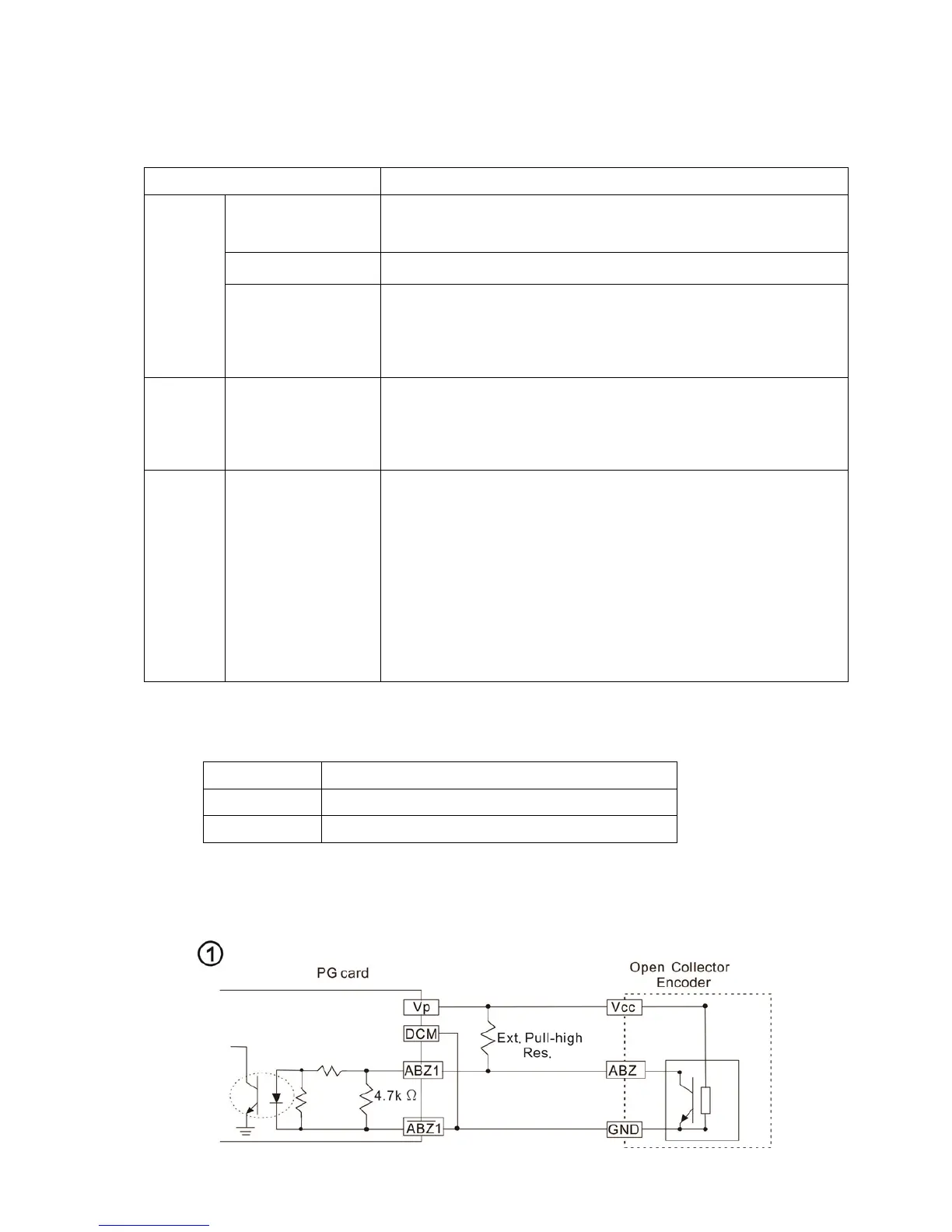
Note 1: Open Collector application, input current 5–15mA to each set then each set needs one pull-up resistor.
If input voltage of open collector is 24V, the power of encoder needs to be connected externally. Please refer to
diagram 2 of PG1.
5V
Recommended pull-up resistor: above 100–220, 1/2W
12V
Recommended pull-up resistor: above 510–1.35k, 1/2W
24V
Recommended pull-up resistor: above 1.8k–3.3k, 1/2W
Note 2: If the required bandwidth is not over 30kHz at the application, it is recommended to use
EMC-PG02O/L (bandwidth 30kHz) to avoid interference.
PG1 card wiring diagram (the image 1 and 2 below are wiring diagrams of Open Collector encoder)
 Loading...