Chapter 8 Option CardsC2000
8-24
8-10 EMC-PG01R -- PG card (Resolver)
8-10-1 Terminal Descriptions
Set by Pr.10-00–10-02 and Pr.10-30 Resolver. (Pr.10-00=3, Pr.10-01=1024)
Terminals Descriptions
PG1
R1- R2
Resolver Output Power
7Vrms, 10kHz
S1, /S3,
S2, /S4,
Resolver Input Signal (S2, /S4=Sin; S1, /S3=Cos)
3.5±0.175Vrms, 10kHz
PG2
A2, /A2,
B2, /B2
Pulse Input signal (Line Driver or Open Collector)
Open Collector Input Voltage: +5–+24V (Note1)
It can be 1-phase or 2-phase input.
Max. output frequency: 300kHz
PG OUT
AO, /AO,
BO, /BO,
ZO, /ZO
,
SG,
PG Card Output signals. It has division frequency function: 1–255
times
Max. output voltage for Line driver: 5V
DC
Max. output current: 15mA
Max. output frequency: 300kHz
SG is the GND of PG card. It is also the GND of position machine or
PLC to make the output signal to be the common pivot point.
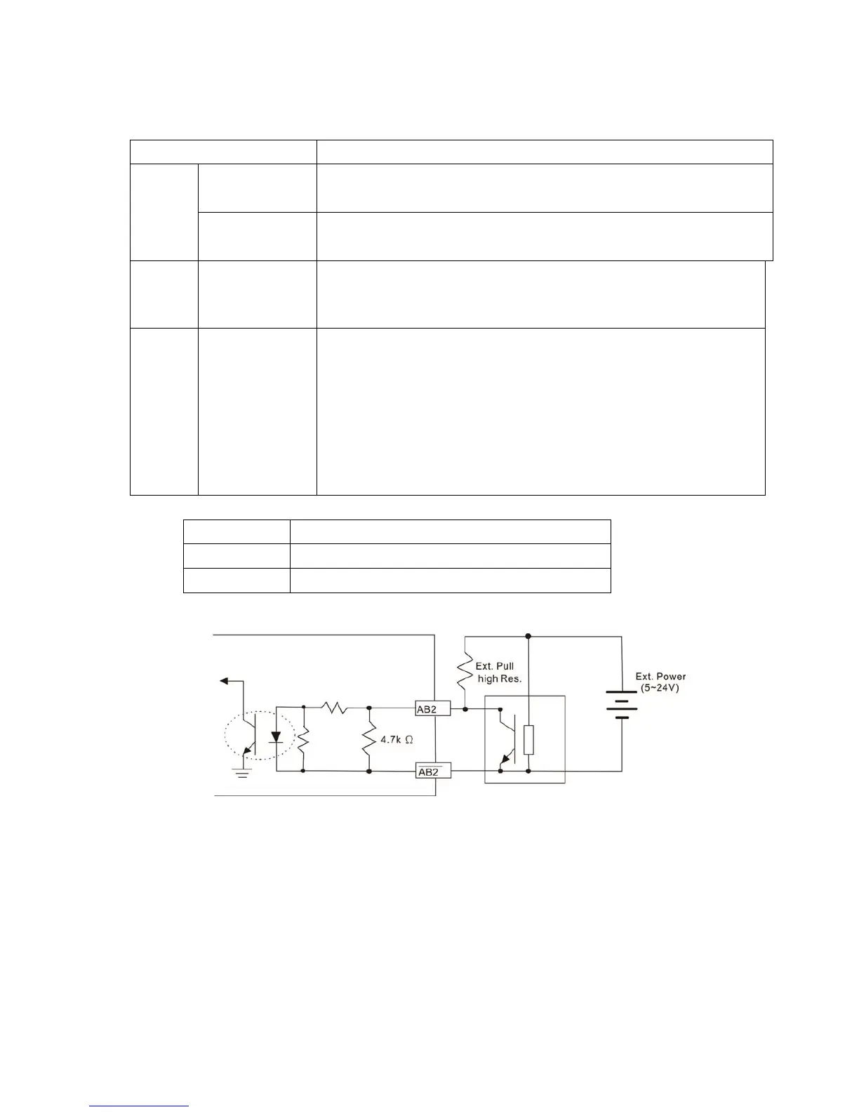
Note 1: Open Collector application, input current 5–15mA to each set then each set needs one pull-up resistor.
5V
Recommended pull-up resistor: above 100–220, 1/2W
12V
Recommended pull-up resistor: above 510–1.35k, 1/2W
24V
Recommended pull-up resistor: above 1.8k–3.3k, 1/2W
PG2 Wiring Diagram
DOS (Degradation of Signal):If the amplitude of the sine wave input of the S1-/S3/ S2-/S4 is lower
than or higher than the encoder IC’s specification, a red light will be on. The possible reasons which
cause this problem are the following.
1. The turns ratio of the resolver encoder is not 1:0.5 which makes the sine wave input of the
S1-/S3/S2-/S4 not equal to 3.5±0.175Vrms.
2. While motor is running, motor creates common mode noise which makes accumulated voltage to
be more than 3.5±0.175Vrms
LOT (Loss of Tracking): Compare the angle of S1-/S3/S2-/S4 sine wave input to the R1-R2 cosine
wave. If their difference is more than 5 degree, a red light will be on. Here are the possible reasons
why that happens:
1. The output frequency of the PG card is incorrect.
2. The specification of Resolver’s encoder is not 10kHz
3. The motor creates common mode noise while it is running. That causes a big difference, while
the motor is rotating, between main winding’s cosine wave angle and the sine wave angle of
second and third windings.
 Loading...