Chapter 8 Option CardsC2000
8-15
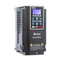
8-5 EMC-A22A -- Extension card for 2-point analog input/ 2-point analog output
Analog I/O
Extension Card
Terminals Descriptions
AI10, AI11
Refer to Pr. 14-00–Pr. 14-01 for function selection (input), and Pr.
14-18–Pr. 14-19 for mode selection.
There are two sets of AI port, SSW3 (AI10) and SSW4 (AI11),
which can be switched to Voltage or Current mode.
Voltage mode: Input 0–10V
Current mode: Input 0–20mA / 4–20mA
AO10, AO11
Refer to Pr. 14-12–Pr. 14-13 for function selection (output), and Pr.
14-36–Pr. 14-37 for mode selection.
There are two sets of AO port, SSW1 (AO10) and SSW2 (AO11),
which can be switched to Voltage or Current mode.
Voltage mode: Output 0–10V
Current mode: Output 0–20mA / 4–20mA
ACM
Analog signal common terminal
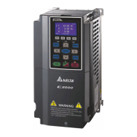
8-6 EMC-BPS01
-- +24V power card
External Power
Supply
Terminals Descriptions
24V
GND
Input power: 24V±5%
Maximum input current: 0.5A
Note:
1) Do not connect drive control terminal GND directly to the
EMC-BPS01 input terminal GND.
Function: When the drive is only powered by EMC-BPS01, the
communication can be assured and support all communication
cards and following functions:
Parameters read and write
Keypad can be displayed
Keypad button can be operated (except RUN)
Analog input is effective
Multi-input (FWD, REV, MI1–MI8) needs external power supply to
operate
Following functions are not supported:
Relay output (including extension card), PG card, PLC function
Note: Refer to I/O & Relay extension card installation/ disconnecting method for PG Card installation/ disconnecting.
 Loading...