Chapter 2 InstallationC2000
2-6
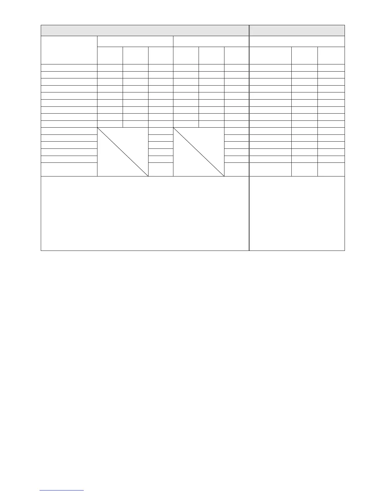
Air flow rate for cooling
Power dissipation of AC motor drive
Model No.
Flow Rate [cfm] Flow Rate [m
3
/hr] Power Dissipation [W]
External Internal Total External Internal Total
Loss External
(Heat sink)
Internal Total
VFD370C63B-21 89.0 21.3 110.3 151.2 36.2 187.5 641.6 283.4 925.0
VFD450C63B-00/21 175.9 36.4 212.3 298.8 61.8 360.6 718.2 406.8 1125.0
VFD550C63B-00/21 175.9 36.4 212.3 298.8 61.8 360.6 890.1 484.9 1375.0
VFD750C63B-00/21 264.6 90.6 355.2 449.6 153.9 603.5 1356.0 519.0 1875.0
VFD900C63B-00/21 264.6 90.6 355.2 449.6 153.9 603.5 1652.8 597.2 2250.0
VFD1100C63B-00/21 264.6 90.6 355.2 449.6 153.9 603.5 1960.3 789.7 2750.0
VFD1320C63B-00/21 264.6 90.6 355.2 449.6 153.9 603.5 2230.8 1069.2 3300.0
VFD1600C63B-00/21 248.1 135.3 383.4 421.6 229.9 651.4 2627.3 1372.7 4000.0
VFD2000C63B-00/21 248.1 135.3 383.4 421.6 229.9 651.4 3415.0 1585.0 5000.0
VFD2500C63B-00/21
409.7
696.0 4751.7 1498.3 6250.0
VFD3150C63B-00/21 409.7 696.0 5695.4 2179.6 7875.0
VFD4000C63B-00/21 563.0 956.4 6796.2 3203.8 10000.0
VFD4500C63B-00/21 952.9 1618.9 7313.6 3936.4 11250.0
VFD5600C63B-00/21 952.9 1618.9 9553.4 4446.6 14000.0
VFD6300C63B-00
VFD6300C63B-21
952.9 1618.9 11042.4 4707.6 15750.0
※ The required airflow shown in chart is for installing single drive in a
confined space.
※ When installing the multiple drives, the required air volume should be the
required air volume for single drive X the number of the drives.
※ The heat dissipation shown in
the chart is for installing single
drive in a confined space.
※ When installing the multiple
drives, volume of heat
dissipation should be the heat
dissipated for single drive X the
number of the drives.
※ Heat dissipation for each model
is calculated by rated voltage,
current and default carrier.
 Loading...