Chapter 5 Main Circuit TerminalsC2000
5-3
Terminals for connecting DC reactor, external brake resistor, external brake resistor
and DC circuit
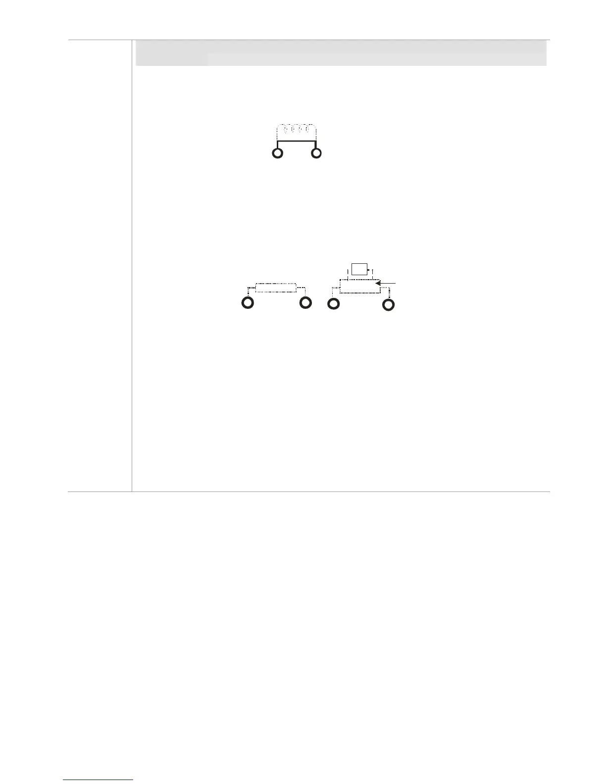
This is the terminals used to connect the DC reactor to improve the power factor. For
the factory setting, it connects the short-circuit object. Please remove this short-circuit
object before connecting to the DC reactor.
+1
+2
DC reactor (optional)
Figure 5-2
Connect a brake resistor or brake unit in applications with frequent deceleration
ramps, short deceleration time, too low brake torque or requiring increased brake
torque.
B1
B2
BR
+
-
VFDB
Brake resistor
(optional)
Brake resistor
(optional)
Brake unit
(optional)
Figure 5-3
The external brake resistor of Frame A, B and C should connect to the terminals (B1,
B2) of AC motor drives.
For those models without built-in brake resistor, please connect external brake unit
and brake resistor (both of them are optional) to increase brake torque.
When the terminals +1, +2 and - are not used, please leave the terminals open.
DC+ and DC- are connected by common DCBUS, please refer to Chapter 5-1 (Main
Circuit Terminal) for the wiring terminal specification and the wire gauge information.
Please refer to the VFDB manual for more information on wire gauge when installing
the brake unit.
 Loading...