52
Wiring the Inverter
CAUTION
Machine and equipment damage may occur.
► Observe the pin assignment of the AC bayonet connector. An incorrect
assignment can result in the unit being destroyed. The Figure 6.5 pin
out diagram shows the connections inside the AC connector.
NOTE
Make sure the line is provided with a strain relief device. When using cables
with a diameter of less than 13 mm (11 mm ... 13 mm diameter cable
require strain relief), the cable must be relieved just behind the connector.
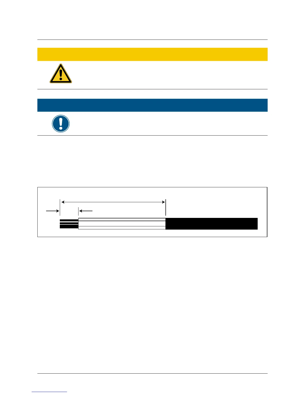
6.2.3 AC bayonet connectors for 30 TL
The AC bayonet connector for 30 TL are approved for cable sheath diameters between 22 mm
and 32 mm. To install an AC cable, rst strip the voltage free line and cable ends as shown below
and then follow the sequence in Figure 6.7 to assemble the cable and bayonnet connector.
60 mm (PE 65 mm)
12 mm
Figure 6.6.: AC cable stripping requirements for 30 TL
In Figure 6.7, the Amphenol PPC AC 24 connector shown can be mated with the 30 TL inverter‘s
AC plug. After disassembly of the connector, please adhere to the correct polarity for proper AC
wiring (this product allows either positive or negative phase sequence). That means the sequence
of L1-L3 can be adjusted and the N and PE must be connected.
 Loading...