Wiring the Inverter
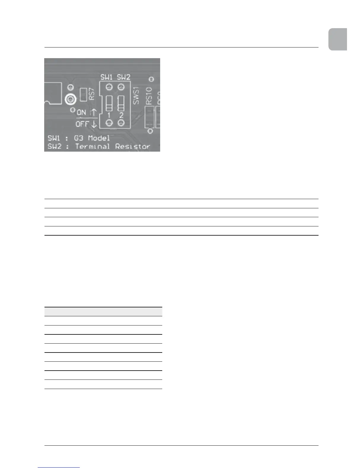
Figure 6.17.: Terminal resistor switch for Multi-inverter Connection
To engage the internal Terminal Resistor, place switch number 2 on the communication module in
the on position. See gure 6.17 for more information.
Baud Rate Programmable, 2400/4800/9600/19200/38400, default = 19200
Data Bit 8
Stop Bit 1
Parity N/A
Table 6.4.: RS485 Data Format
6.5.2 EPO (Emergency Power Off) Connections
The SOLIVIA 10 TL / 15 TL / 20 TL / 30 TL provides two sets of emergency power off functions.
When the outer external switch is shorted, the inverter will shut down immediately. Please see
Table 6.5 for the pin denition.
PIN
1 EPO1
2 EPO1
3 N/A
4 EPO2
5 EPO2
6 N/A
7 N/A
8 N/A
Table 6.5.: EPO pin assignment
 Loading...