Operating the PV inverter
Notes:
In the formulas on the previous page, the
parameters mentioned are named differently
as in the menu page
Curve A (in blue) Figure 6.30
Point A = Plockout = Lower Power
Point B = Plockin = Upper Power
Point C = Lower limit • cosφ
Curve A is followed when Lower Power is not
equal to Upper Power
Curve B (in Red) Figure 6.30
Point A (Lower Power) = Point B (Upper
Power)
Point C = Lower limit • cosφ
Curve B is followed when Lower Power =
Upper Power
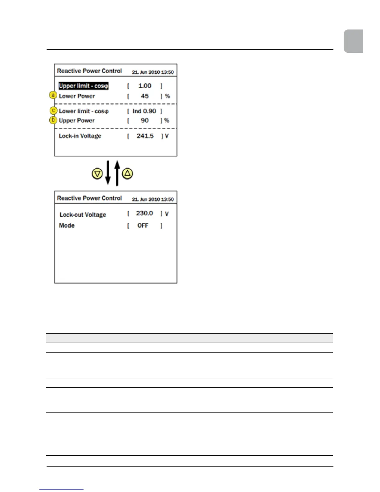
Figure 7.32.: cos φ(P) settings page
Adjustable parameters for
Parameter Adjustable values Curve A Curve B
Upper limit - cos φ Ind 0.80 ... Cap 0.80 Cap 1.0 Cap 1.0
Lower Power 0 ... 100 % 45% is shown but
adjust to grid operator
requested value
should equal Upper
Power
Lower limit - cos φ Ind 0.80 ... Cap 0.80 Ind 0.90 Ind 0.90
Upper Power 0 ... 100 % 90% is shown but
adjust to grid operator
requested value
should equal Lower
Power
Lock-in Voltage* 230-253 V 241.5 V is default value and is 1.05Vn (Vn =
230V)
Lock-out Voltage* 207-230 V 230 V is default value (adjustable at 0.98 Vn
to Vn; Vn=230V). When the grid voltage ≤ the
Lock-out voltage
 Loading...