Pin Description Pin Description
5 Encoder Channel A- - -
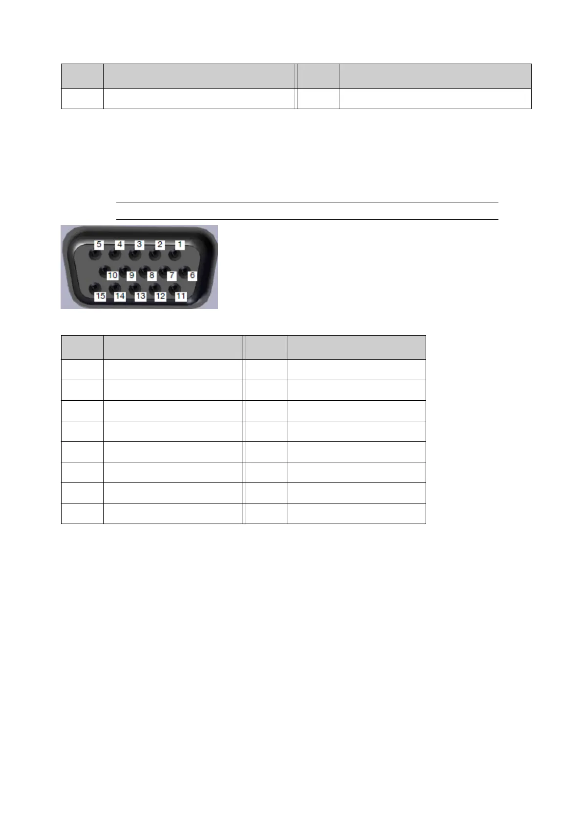
Print Head Connector Layout
Gx-IC7 controllers have 2 print head connectors.
Gx-IC10 and Gx-OEM controllers have 4 Print Head connectors.
The pin assignments are illustrated below.
Note Use a Domino print head cable to connect print heads to the controller.
High-Density D-Sub Socket (External View)
Pin Description Pin Description
1 Tx- (Transmit -) 9 Not Used
2 Ground 10 24 V
3 Tx+ (Transmit +) 11 24 V
4 DET (Detector) 12 Ground
5 Ground 13 Ground
6 Rx+ (Receive +) 14 Rx- (Receive -)
7 Not Used 15 Ground
8 Not Used - -
I/O Connector Layout (Gx-IC7)
The Gx-IC7 controller has 2 I/O connectors.
Both connectors have the same pin assignments as shown below.
INSTALLATION
37 EPT053091 - Issue 5 - 07 May 2021
 Loading...