FAULT FINDING AND REPAIR
20509 Issue 7 Jan 2018 4-25
Pump Replacement
The pump is a reliable unit and before being replaced all other possible
causes of failure to pressurise the system should be investigated. This
includes leaks in the system.
The printer must be switched off and the power removed. Remove the
cabinet cover and place tissue in the cabinet base to catch escaping ink.
(1) Depressurise the ink system.
(2) Note the positions of the wires, then desolder the motor wiring.
(3) Open the bleed valve on the rear panel to vent the system.
(4) Close the bleed valve.
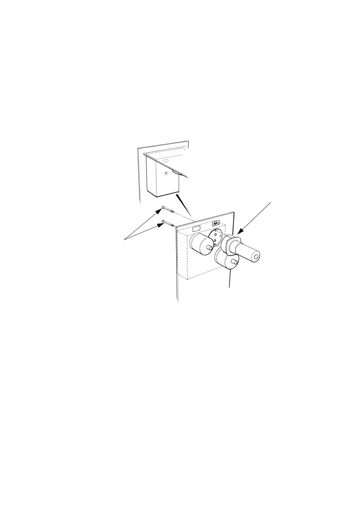
(5) Remove the two cap head screws securing the pump.
Note: The securing screws are in recesses in the accumulator side of
the manifold. They are not the screws around the pump motor
flange. A 2.5mm ball end driver is required for the top screw
and an Allen key for the bottom screw.
(6) Remove the pump and clean pump housing area with wash solution.
(7) Fit new O-Rings into the pump manifold.
(8) Make sure the new pump has a capacitor fitted across the terminals.
(9) Refit the pump to the manifold block.
(10) Resolder motor wiring (violet wire to + terminal).
(11) Prime the system (see page 4-17).
TP33984-2
Securing
Screws
Pump
 Loading...