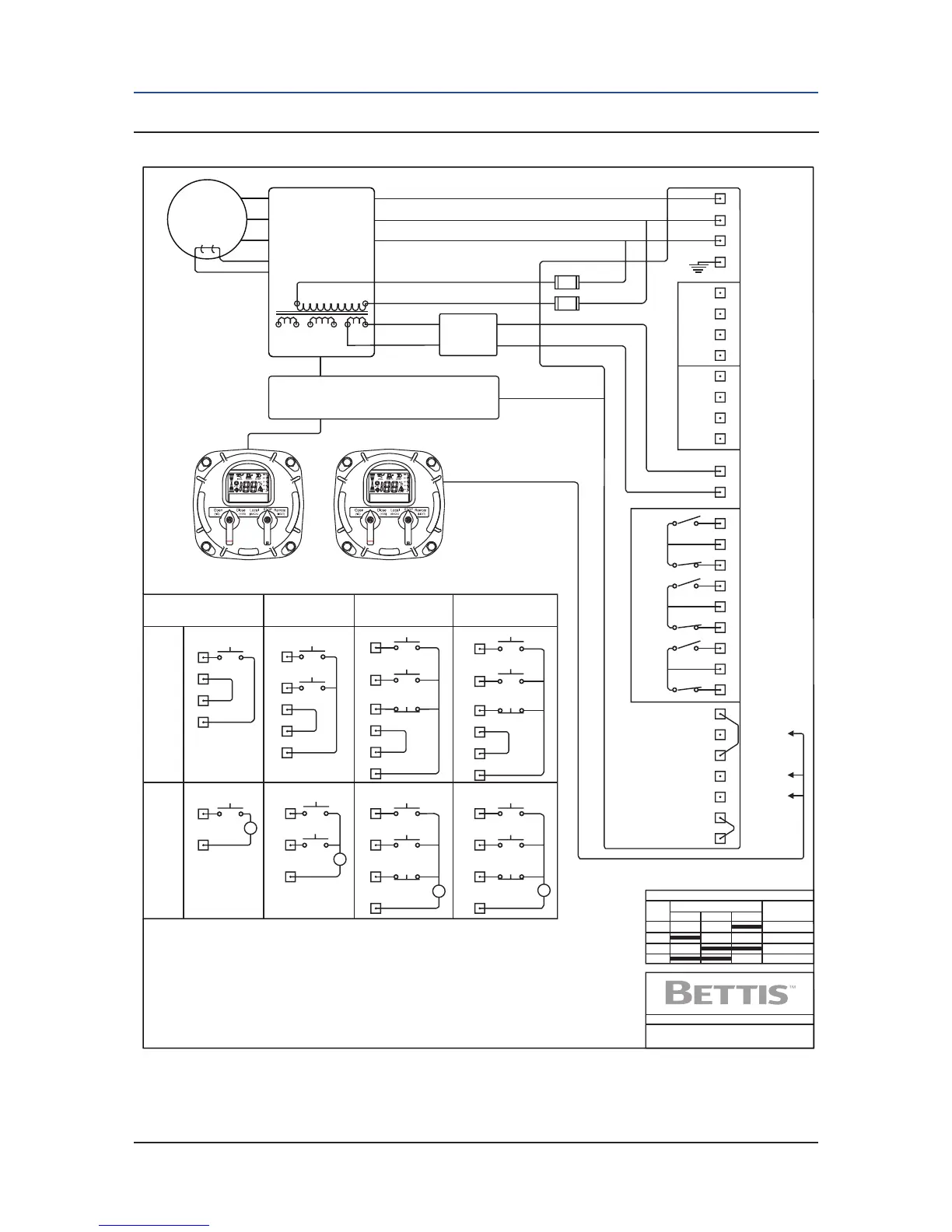
Figure 3-22 TEC2 Wiring Diagram
NOTE:
The Local Display Module (LDM) is a part of the actuator and is powered internally by a low voltage DC.
The Remote Display Module (RDM) is powered by two options, either 24VDC or 90-250VAC 50/60Hz.
Z
Z
Z
Z
Central Control Module
Note: Maximum Power Rating: 15.12 Watts
Maximum Source Current: 0.63 Amps
Two-Wire Control
Maintain Contact to Open
Open
+24 VDC
+24 VDC
+24 VDC
+24 VDC
Internal
Power
Supply
Open
Open
Open
Common 0V
Common 0V
Common 0V Common 0V
Open
Open Open Inhibit
Open Inhibit
Close Inhibit
Close Inhibit
Output Switch Contact Development
Valve Position
Contact
Function
Close
DWN BY JTD ORIGINAL DATE 4-21-03
LSO
LSC
LSA
LSB
WIRING
DIAGRAM
TEC-001
MID
Open
Open Limit
Close Limit
Close Limit
Open Limit
Close
Stop
0V
0V
0V
0V
Stop
ESD
ESD
Close
Close
Close
External
Power
Supply
18-150 VDC
or
20-250 VAC
Three-Wire Control
Maintained Contacts
Local Display Module Remote Display Module
(1 or 2 May be fitted)
Four-Wire Contol
Momentary Contacts
Inhibit/Interlock
and ESD
24 VDC
Power
Supply
3 - Phase
Power
L3
L2
L1
1
2
3
4
5
6
7
8
11
12
13
14
15
16
17
18
19
11
1
5
6
7
8
10
2
3
4
9
9
10
2
4
9
10
4
10
9
1
11
2
3
4
5
6
7
8
2
4
4
20
21
22
23
24
36
38
9
10
GND
Supply
Open
Close
Stop
Common 0V
Common 0V
ESD
+24 VDC
LSOR0#1
R0#2
R0#3
R0#4
R0#5
LSC
LSB
LSA
Common
Common
Common
Monitor
Relay
N.O. Contact
N.C. Contact
RS485 (+)
RS485 (-)
Separate
Terminal
Chamber
Shield
DCMlink
TM
Emergency
Stop
Emergency
Stop
0 VDC
Open Inhibit
Close Inihbit
Motor
Motor
Control
Module
Contact Outputs
Digital Inputs
Thermal
Protector
NOTES: 1) All digital inputs have an input votage range or 18-150 VDC or 20-250 VAC.
2) All digital relay outputs are rated for 5A @ 30 VDC or 5A @ 250 VAC Resistive, 2A inductive load.
3) Jumpers shown connected between terminals are permissible but not required.
4) Emergency stop requires jumper or normally closed contact (actuator stops when contact open)
5) Remote display communication port is RS-485.
6) If bare wires (without terminals) are connected, remove a maximum of .25 inch insulation
.
7) User replaceable primary fuses (F1 and F2) are located in the Terminal Chamber Enclosure.
All transformer secondary fuses are automatic resetting.
8) Contacts Outputs and Output Switch Contact Development Chart shown for default configuration only.
User may redefine all Outputs (See TEC200O Installation & Operation Manual E2K-405-0902).
+
+
-
+
-
+
-
-

 Loading...