Relays #9 through #12 are the auxiliary relays when the Auxiliary Relay Module
(ARM) is installed. To congure these relay outputs, follow Step No.1 through
No. 3 listed above. See Table 5-3.
NOTE:
The ARM cannot be added when the Controlinc ACM is installed.
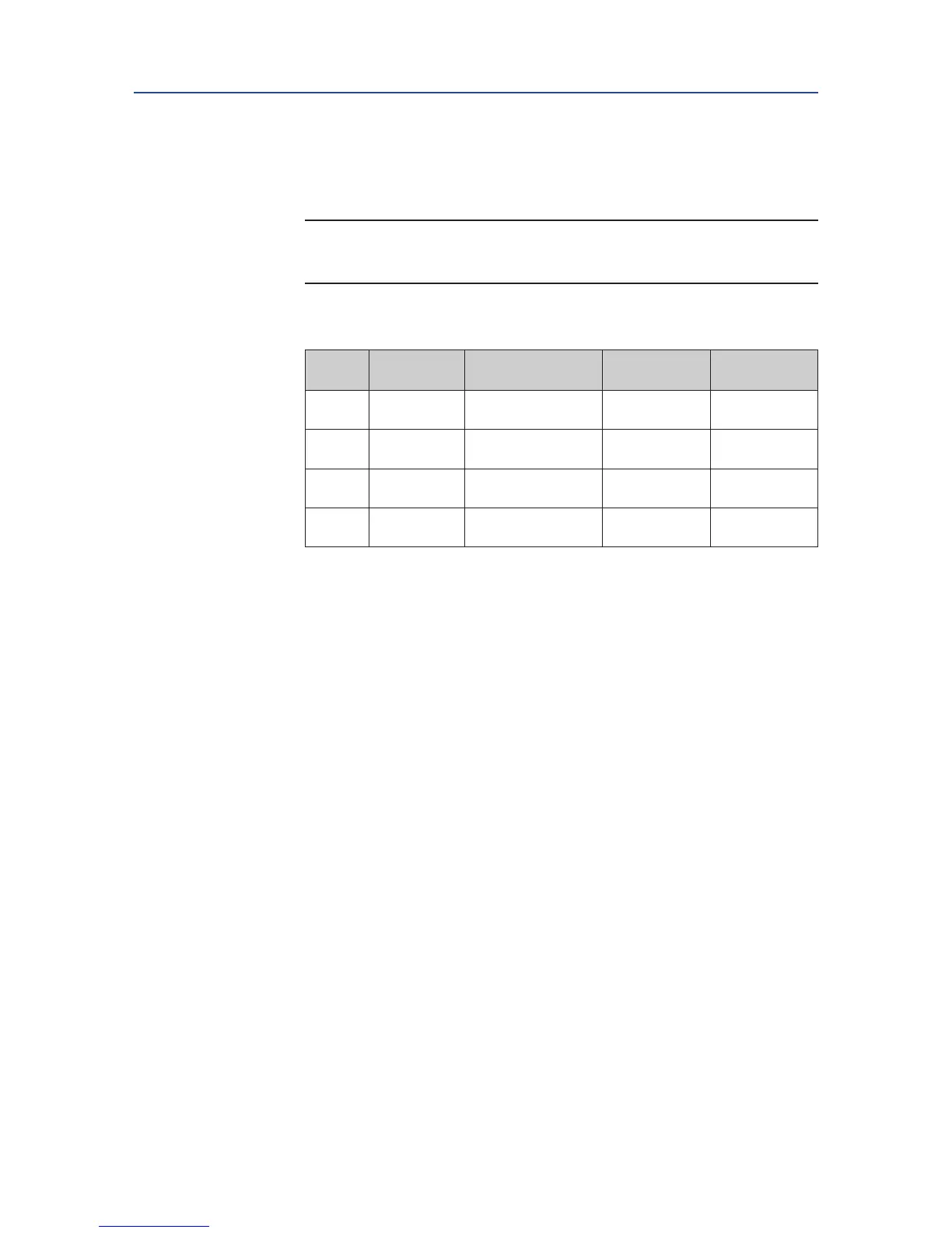
Table 5-3. Relay Outputs #9 through #12 Configuration
Relay
Default
Function
Configurable
Function
Configure
N.O./N.C.
Default
Setting
RO#9 Lost Power
See Table 5-2 Relay
Output Function List
Yes N.O.
RO#10 Motor Overload
See Table 5-2 Relay
Output Function List
Yes N.O.
RO#11 Lost Phase
See Table 5-2 Relay
Output Function List
Yes N.O.
RO#12 Over Torque
See Table 5-2 Relay
Output Function List
Yes N.O.
5.5.6 Inhibit and ESD Setup
1. At the “INHIBIT AND ESD SETUP?” prompt answer “YES.”
2. Use the selector knob (NEXT/BACK) to review the settings for Control
Inhibits and Emergency Shut Down.
3. Use the control knob (NO) to select either ON or OFF for each setting;
then answer “YES.”
Figure 5-11 details each setting.

 Loading...