Safety
Information
Product
information
Mechanical
installation
Electrical
installation
Getting
started
Basic
parameters
Running the
motor
Optimization
EtherCAT
interface
SMARTCARD
Operation
Onboard
PLC
Advanced
parameters
Technical
Data
Diagnostics
UL listing
information
164 Digitax ST User Guide
Issue Number: 5
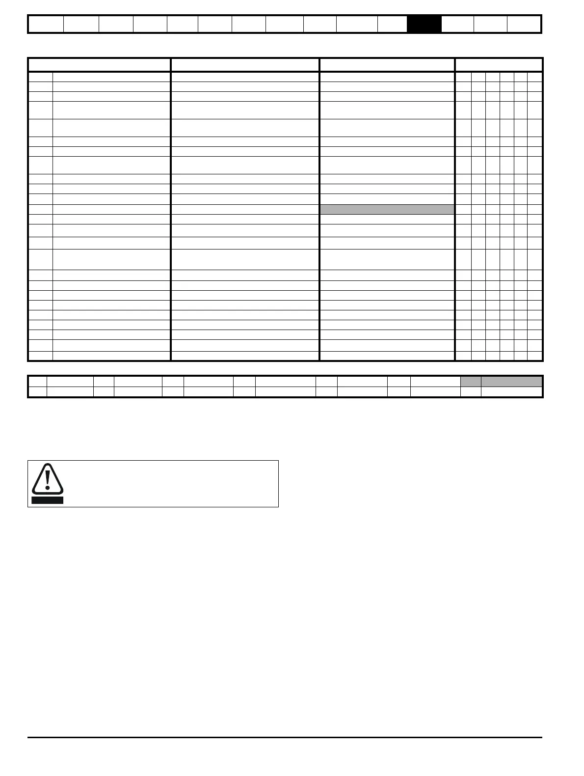
12.20 Menu 21: Second motor parameters
* The menu 0 references are only valid when the second motor map parameters have been made active by setting Pr 11.45 to 1. (The second motor
map only becomes effective when the output stage of the drive is not enabled, i.e. inh, rdY, or trip states.)
When the second motor map parameters are active, the symbol ‘Mot2’ will appear in the lower left hand corner of the LCD display or the decimal point
that is second from the right on the first row of the LED display is lit.
Parameter
Range(
Ú)Default(Ö)
Type
21.01 Maximum reference clamp {0.02}* SPEED_LIMIT_MAX rpm 3,000.0 RW Uni US
21.02 Minimum reference clamp {0.01}* ±SPEED_LIMIT_MAX rpm 0.0 RW Bi PT US
21.03 Reference selector {0.05}*
A1.A2 (0), A1.Pr (1), A2.Pr (2), Pr (3), PAd (4), Prc (5)
A1.A2 (0) RW Txt US
21.04 Acceleration rate {0.03}*
0.000 to 3,200.000
s/1000rpm
0.200 RW Uni US
21.05 Deceleration rate {0.04}*
0.000 to 3,200.000
s/1000rpm
0.200 RW Uni US
21.07 Rated current {0.46}* 0 to RATED_CURRENT_MAX A Drive rated current (Pr 11.32) RW Uni RA US
21.08 Rated speed 0.00 to 40,000.00 rpm 3,000.00 RW Uni US
21.09 Rated voltage {0.44}* 0 to AC_VOLTAGE_SET_MAX V
200V rating drive: 230V
400V rating drive: EUR> 400V, USA> 460V
RW Uni RA US
21.11 Number of motor poles {0.42}* Auto to 120 pole (0 to 60) 6 POLE (3) RW Txt US
21.12 Stator resistance 0.000 to 65.000 x 10
Ω 0.0 RW Uni RA US
21.14
Transient inductance (
σL
s)
0.000 to 500.000mH 0.000 RW Uni RA US
21.15 Motor 2 active OFF (0) or On (1)
RO Bit NC PT
21.16 Thermal filter {0.45}* 0.0 to 3000.0 20.0 RW Uni US
21.17 Speed controller Kp gain {0.07}*
0.000 to 6.5535 rad s
-1
0.0100 RW Uni US
21.18 Speed controller Ki gain {0.08}*
0.00 to 655.35 s/rad s
-1
1.00 RW Uni US
21.19 Speed controller Kd gain {0.09}*
0.00000 to 0.65535
s
-1
/rad s
-1
0.00000 RW Uni US
21.20 Encoder phase angle** {0.43}*
0.0 to 359.9
° electrical
0.0 RW Uni US
21.21 Speed feedback selector drv (0), SLot1 (1), SLot2 (2), SLot3 (3) drv (0) RW Txt US
21.22 Current controller Kp gain {0.38}* 0 to 30,000 200V: 75, 400V: 150, RW Uni US
21.23 Current controller Ki gain {0.39}* 0 to 30,000 200V: 1,000, 400V: 2,000, RW Uni US
21.27 Motoring current limit 0 to MOTOR2_CURRENT_LIMIT_MAX % 300.0 RW Uni RA US
21.28 Regen current limit 0 to MOTOR2_CURRENT_LIMIT_MAX % 300.0 RW Uni RA US
21.29 Symmetrical current limit {0.06}* 0 to MOTOR2_CURRENT_LIMIT_MAX % 300.0 RW Uni RA US
21.30
Motor volts per 1,000 rpm, K
e
SV> 0 to 10,000 V 98 RW Uni US
21.31 Motor pole pitch 0.00 to 655.35 mm 0.00 RW Uni US
RW Read / Write RO Read only Uni Unipolar Bi Bi-polar Bit Bit parameter Txt Text string
FI Filtered DE Destination NC Not copied RA Rating dependent PT Protected US User save PS Power down save
**Encoder phase angle
The encoder phase angles in Pr
3.25
and Pr
21.20
are copied
to the SMARTCARD when using any of the SMARTCARD
transfer methods.

 Loading...