Safety
Information
Product
information
Mechanical
installation
Electrical
installation
Getting
started
Basic
parameters
Running the
motor
Optimization
EtherCAT
interface
SMARTCARD
Operation
Onboard
PLC
Advanced
parameters
Technical
Data
Diagnostics
UL listing
information
Digitax ST User Guide 37
Issue: 5
Refer to section 4.17 Safe Torque Off on page 42 for further information.
4.15 Encoder connections
Figure 4-11 Encoder
4.15.1 Location of encoder connector
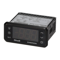
Before using the encoder connectors for the first time, the break-outs
need removing as shown in Figure 4-12.
Figure 4-12 Access to encoder connections
Do not remove break-out if the connections are not required.
Figure 4-13 Connecting the encoder ground tab to the EMC
bracket
The size of the connecting cable between the encoder ground tab and
the EMC bracket should be equal to the input cable.
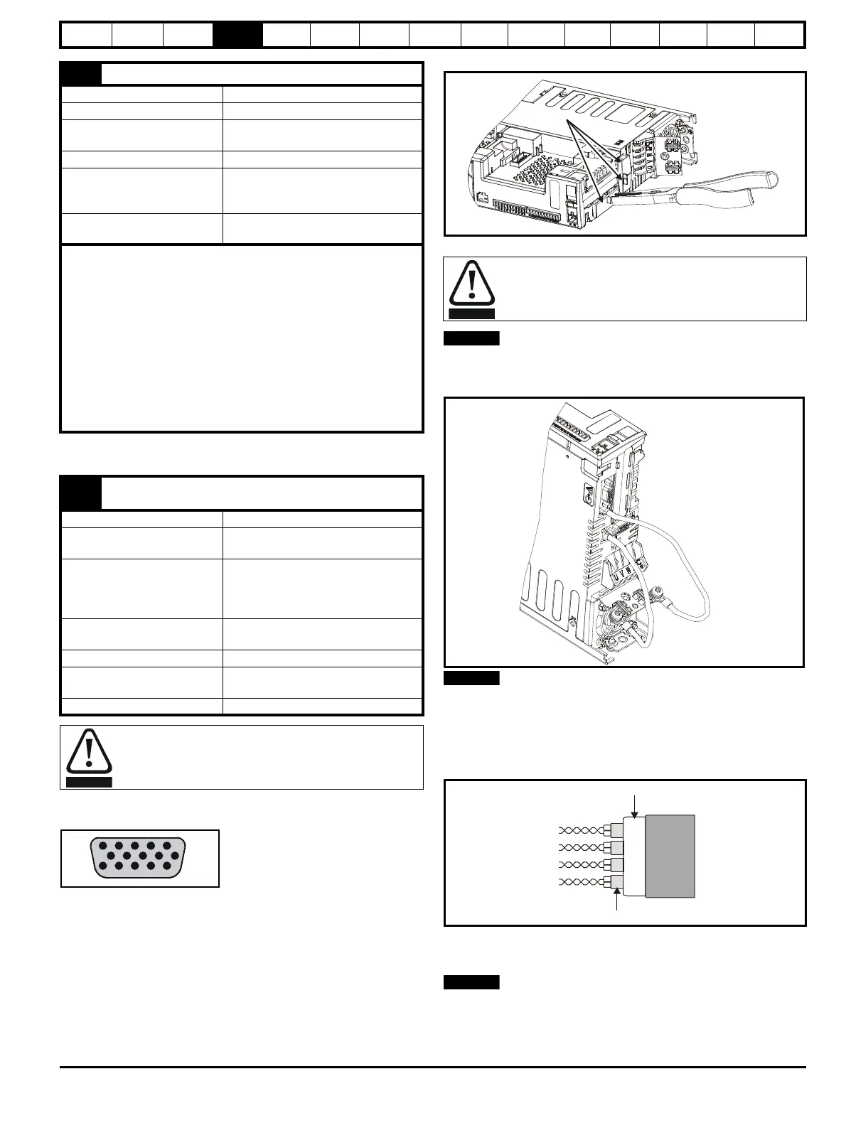
Recommended cable
The recommended cable for feedback signals are shielded twisted pairs,
shielded with an overall shield as shown in Figure 4-14.
Figure 4-14 Feedback Cable, Twisted Pairs
Using this type of cable also allows for the connection of the outer shield
to ground and the inner shields to 0V alone at both drive and encoder
end, when required.
Ensure that feedback cables are kept as far away as possible from
power cables and avoid parallel routing.
31 Safe Torque Off function (drive enable)
Type Positive logic only digital input
Voltage range 0V to +24 V
Absolute maximum applied
voltage
±30 V
LogicThreshold 15.5 V ±2.5 V
Low state maximum voltage
for SIL3 and EN954-1
category 3
2 V (or open-circuit)
Response time
Nominal: 8 ms
Maximum: 20 ms
Safe Torque Off function has been approved by IFA as meeting the
requirements of the following standards, for the prevention of
unexpected starting of the drive:
EN 61800-5-2:2007 SIL 3
EN ISO 13849-1:2006 PL e
EN 954-1:1997 Category 3 (This standard is withdrawn and
should not be used for new designs, information provided for
legacy applications only).
The Safe Torque Off function may be used in a safety-related
application in preventing the drive from generating torque in the motor
to a high level of integrity. The system designer is responsible for
ensuring that the complete system is safe and designed correctly
according to the relevant safety standards.
41
Relay contacts
42
Default function Drive OK indicator
Contact voltage rating
240 Vac, Installation over-voltage
category II
Contact maximum current
rating
2 A AC 240 V
4 A DC 30 V resistive load
0.5 A DC 30 V inductive load (L/R =
40 ms)
Contact minimum
recommended rating
12 V 100 mA
Contact type Normally open
Default contact condition
Closed when power applied and drive
OK
Update period 4 ms
A fuse or other over-current protection should be Installed to
the relay circuit.
After removing the break-out, ensure that the ground tab is
connected to ground (see Figure 4-13). This will connect 0V
of the drive to ground. This is required to enable the drive to
meet IP20 when the break-out is removed.
Twisted
pair
cable
Twisted pair shield
Cable
Cable overall shield

 Loading...