Safety
Information
Product
information
Mechanical
installation
Electrical
installation
Getting
started
Basic
parameters
Running
the motor
Optimization
EtherCAT
interface
SMARTCARD
Operation
Onboard
PLC
Advanced
parameters
Technical
Data
Diagnostics
UL listing
information
Digitax ST User Guide 65
Issue: 5
7.3 Setting up a feedback device
This section shows the parameter settings which must be made to use each of the compatible encoder types with Digitax ST. For more information
on the parameters listed here please refer to the Advanced User Guide.
7.3.1 Overview
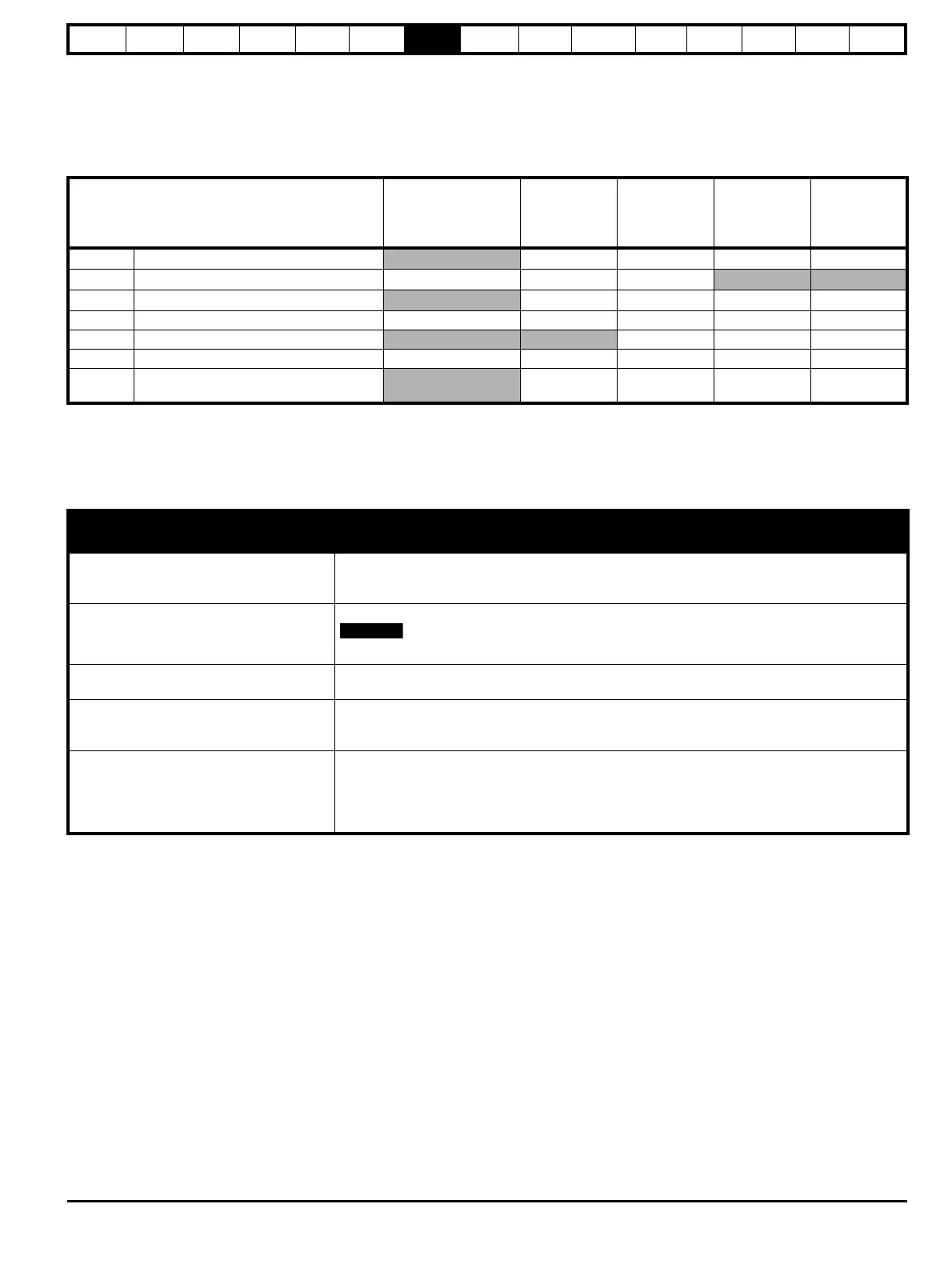
Table 7-3 Parameters required for feedback device set-up
Parameter
Ab, Fd, Fr,
Ab.SErVO,
Fd.SErVO, Fr.SErVO,
or SC encoders
SC.HiPEr
encoder
SC.EndAt or
SC.SSI
encoders
EndAt
encoder
SSI encoder
3.33 Drive encoder turns
9 x 9 x 9 x
9
3.34 Drive encoder lines per revolution 9
9 x 9 x
3.35 Drive encoder comms resolution
9 x 9 x 9 x
9
3.36 Drive encoder supply voltage* 9 9999
3.37 Drive encoder comms baud rate
999
3.38 Drive encoder type 9 9999
3.41
Drive encoder auto configuration enable or
SSI binary format select
9999
9 Information required
x Parameter can be set-up automatically by the drive through auto-configuration
* Pr 3.36: If A + B >5 V then disable termination resistors
Table 7-3 shows a summary of the parameters required to set-up each feedback device. More detailed information follows.
7.3.2 Detailed feedback device set-up information
Standard quadrature encoder with or without commutation signals (A, B, Z or A, B, Z, U, V, W), or
Sincos encoder without serial communications
Encoder type Pr 3.38
Ab (0) for a quadrature encoder without commutation signals
Ab.SErVO (3) for a quadrature encoder with commutation signals
SC (6) for a Sincos encoder without serial communications
Encoder power supply voltage Pr 3.36
5 V (0), 8 V (1) or 15 V (2)
If Ab encoder voltage is greater than 5 V, then the termination resistors must be disabled Pr 3.39 to 0
Encoder number of lines per
revolution
Pr 3.34 Set to the number of lines or sine waves per revolution of the encoder.
Encoder termination selection
(Ab or Ab.SErVO only)
Pr 3.39
0 = A, B, Z termination resistors disabled
1 = A, B termination resistors enabled and Z termination resistors disabled
2 = A, B, Z termination resistors enabled
Encoder error detection level Pr 3.40
0 = Error detection disable
1 = Wire break detection on A, B and Z inputs enabled
2 = Phase error detection (Ab.SErVO only)
3 = Wire break detection on A, B and Z inputs and phase error detection (Ab.SErVO only)
Termination resistors must be enabled for wire break detection to operate

 Loading...