Safety
Information
Product
information
Mechanical
installation
Electrical
installation
Getting
started
Basic
parameters
Running the
motor
Optimization
EtherCAT
interface
SMARTCARD
Operation
Onboard
PLC
Advanced
parameters
Technical
Data
Diagnostics
UL listing
information
20 Digitax ST User Guide
Issue: 5
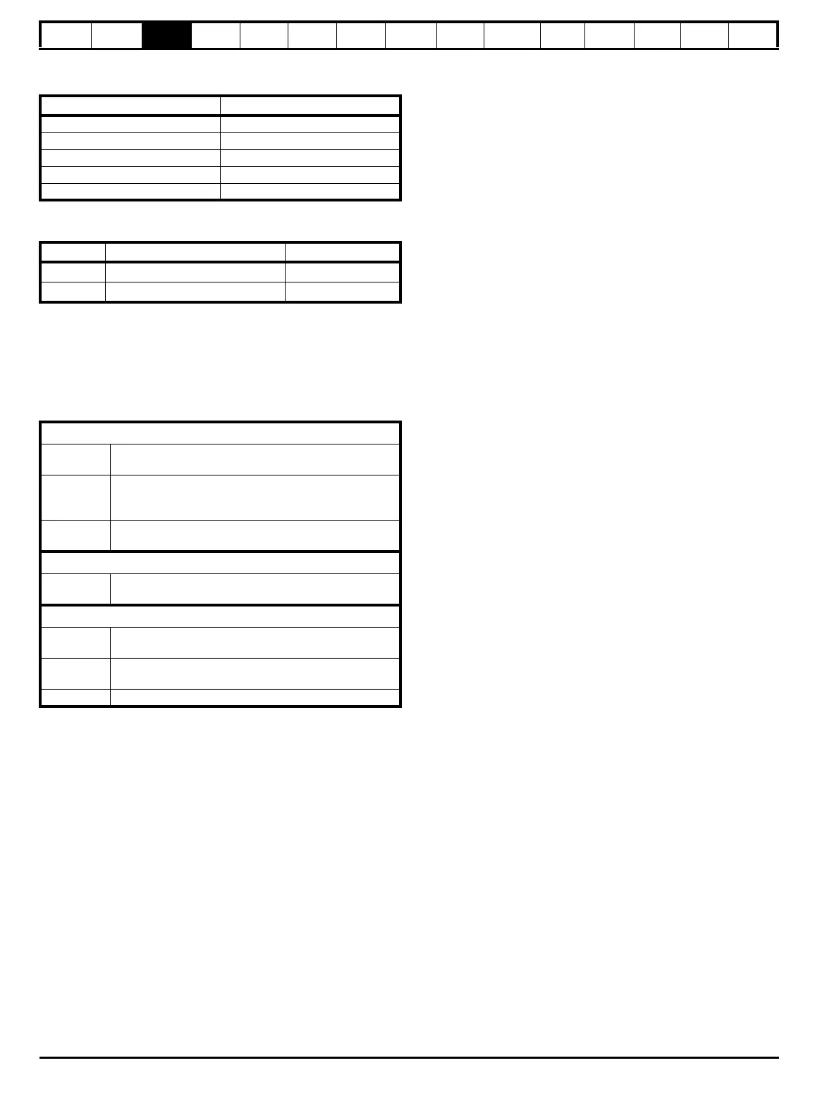
3.7 Terminal torque settings
Table 3-2 Torque settings
*Torque tolerance = 10 %
Table 3-3 Plug-in terminal block maximum cable sizes
3.8 Routine maintenance
The drive should be installed in a cool, clean, well ventilated location.
Contact of moisture and dust with the drive should be prevented.
Regular checks of the following should be carried out to ensure drive /
installation reliability are maximized:
Terminals Torque setting*
Power terminals 1.0 N m (12.1 lb in)
Control terminals 0.2 N m (1.7 lb in)
Status relay terminals 0.5 N m (4.5 lb in)
Ground terminals 4 N m (35 lb in)
Small ground terminal screws 2 N m (17.7 lb in)
Model size Terminal block description Max cable size
All 11 way control connectors
1.5 mm
2
(16 AWG)
All 2 way relay connector
2.5 mm
2
(12 AWG)
Environment
Ambient
temperature
Ensure the enclosure temperature remains at or below
maximum specified
Dust
Ensure the drive remains dust free – check that the
heatsink and drive fan are not gathering dust. The
lifetime of the fan is reduced in dusty environments.
Moisture
Ensure the drive enclosure shows no signs of
condensation
Enclosure
Enclosure
door filters
Ensure filters are not blocked and that air is free to flow
Electrical
Screw
connections
Ensure all screw terminals remain tight
Crimp
terminals
Ensure all crimp terminals remains tight – check for any
discoloration which could indicate overheating
Cables Check all cables for signs of damage

 Loading...