Safety
Information
Product
information
Mechanical
installation
Electrical
installation
Getting
started
Basic
parameters
Running the
motor
Optimization
EtherCAT
interface
SMARTCARD
Operation
Onboard
PLC
Advanced
parameters
Technical
Data
Diagnostics
UL listing
information
Digitax ST User Guide 19
Issue: 5
Figure 3-11 External EMC filter dimensions
Figure 3-11 shows a 3 phase filter. For a single phase filter, there are only 3 input terminals (L1, N, ground) and 3 output cables (L1, N, ground).
3.6 Optional braking resistor
3.6.1 Optional internal braking resistor
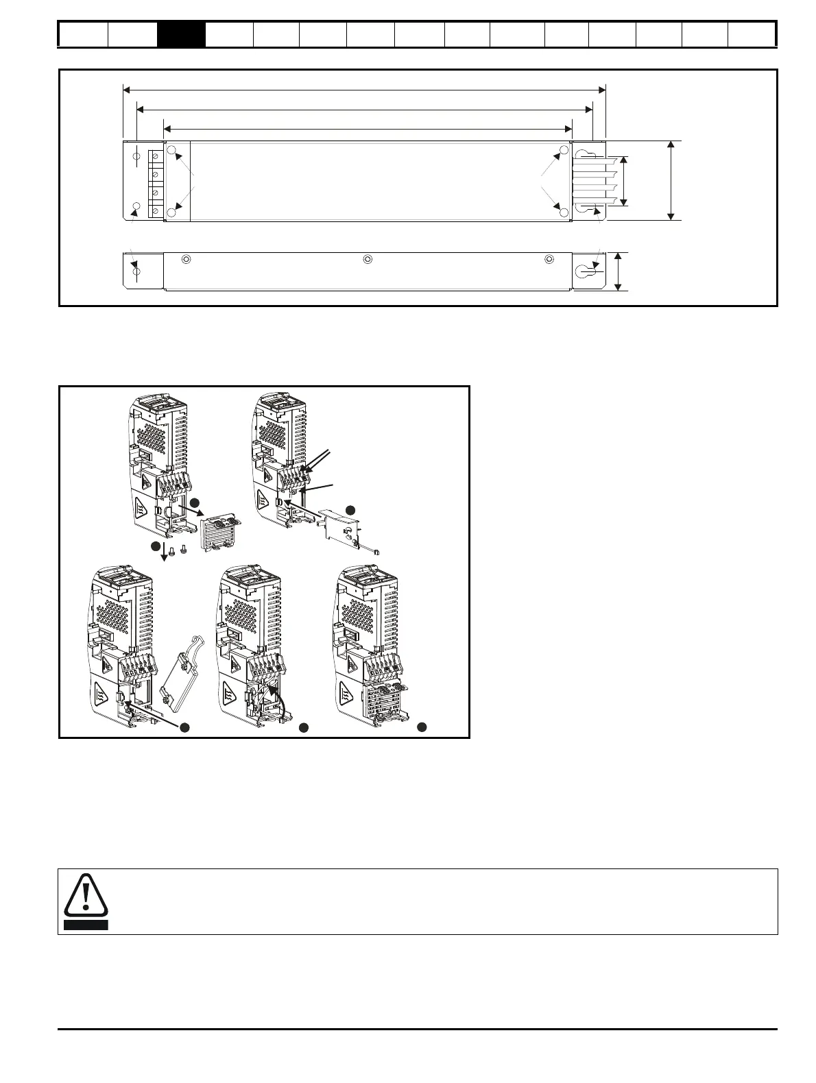
Figure 3-12 Installing an optional internal braking resistor (top view of drive)
1. Remove screws.
2. Remove grill.
3. Install the braking resistor shield.
4. Install the optional internal braking resistor in the slot provided (note the angle).
5. Electrically connect the braking resistor and thermistor (connections shown in Figure 4-1 Power terminal connections on page 22).
6. Re-install the grill and mounting screws by reversing the procedure in points 1 and 2.
3.6.2 Optional external braking resistor
If using an external braking resistor, the following Warning must be adhered to:
Braking resistor: High temperatures and overload protection
Braking resistors can reach high temperatures. Locate braking resistors so that damage cannot result. Use cable having insulation capable
of withstanding the high temperatures.
359mm (14.13in)
339mm (13.35in)
304mm (11.97in)
38mm
(1.50in)
61mm
(2.40in)
M5 M5
Torque settings of connector = 0.8 N m
∅
5.3mm (M5)
(0.21in)
∅
5.3mm (M5)
(0.21in)
4
2
1
Brake
connections
Thermistor
connection
3
5
6

 Loading...