Safety
Information
Product
information
Mechanical
installation
Electrical
installation
Getting
started
Basic
parameters
Running the
motor
Optimization
EtherCAT
interface
SMARTCARD
Operation
Onboard
PLC
Advanced
parameters
Technical
Data
Diagnostics
UL listing
information
22 Digitax ST User Guide
Issue: 5
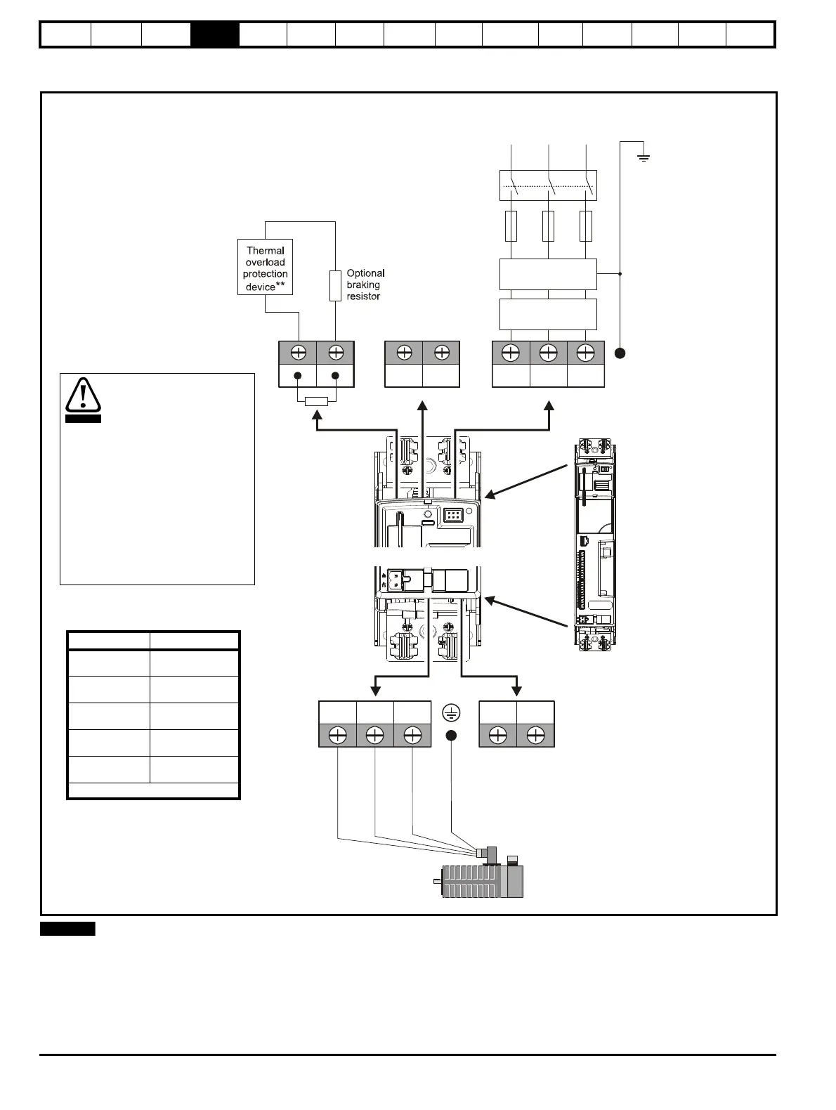
4.1 Power terminal connections
Figure 4-1 Power terminal connections
* When using a 200 V drive on a single phase supply, the live and neutral conductors can be connected to any of the AC connections on the drive.
** This is not required if the optional internal braking resistor is used.
Fuses
L3
*
Mains
supply
Supply
ground
DST12XX = 200 to 240V 10%
DST14XX = 380 to 480V 10%
±
±
Connectors specification:
Maximum size of power cable
= 4.0mm (10AWG)
Torque setting = 1 N m
2
It is essential that the braking
resistor be protected against
overload caused by a failure
of the brake control. Unless
the resistor has in-built
protection, a circuit like those
shown in Figure 4-1 should
be used, where the thermal
protection device
disconnects the AC supply to
the drive. Do not use AC
relay contacts directly in
series with the braking
resistor circuit, because it
carries DC.
Terminals Torque setting
Power terminals
1.0 N m
(12.1 lb in)
Control terminals
0.2 N m
(1.7 lb in)
Status relay
terminals
0.5 N m
(4.5 lb in)
Ground terminal
screws
4 N m
(35 lb in)
Small ground
terminal screws
2 Nm
(17.7 Ib in)
* *Torque tolerance = 10%

 Loading...