Safety
Information
Product
information
Mechanical
installation
Electrical
installation
Getting
started
Basic
parameters
Running the
motor
Optimization
EtherCAT
interface
SMARTCARD
Operation
Onboard
PLC
Advanced
parameters
Technical
Data
Diagnostics
UL listing
information
34 Digitax ST User Guide
Issue: 5
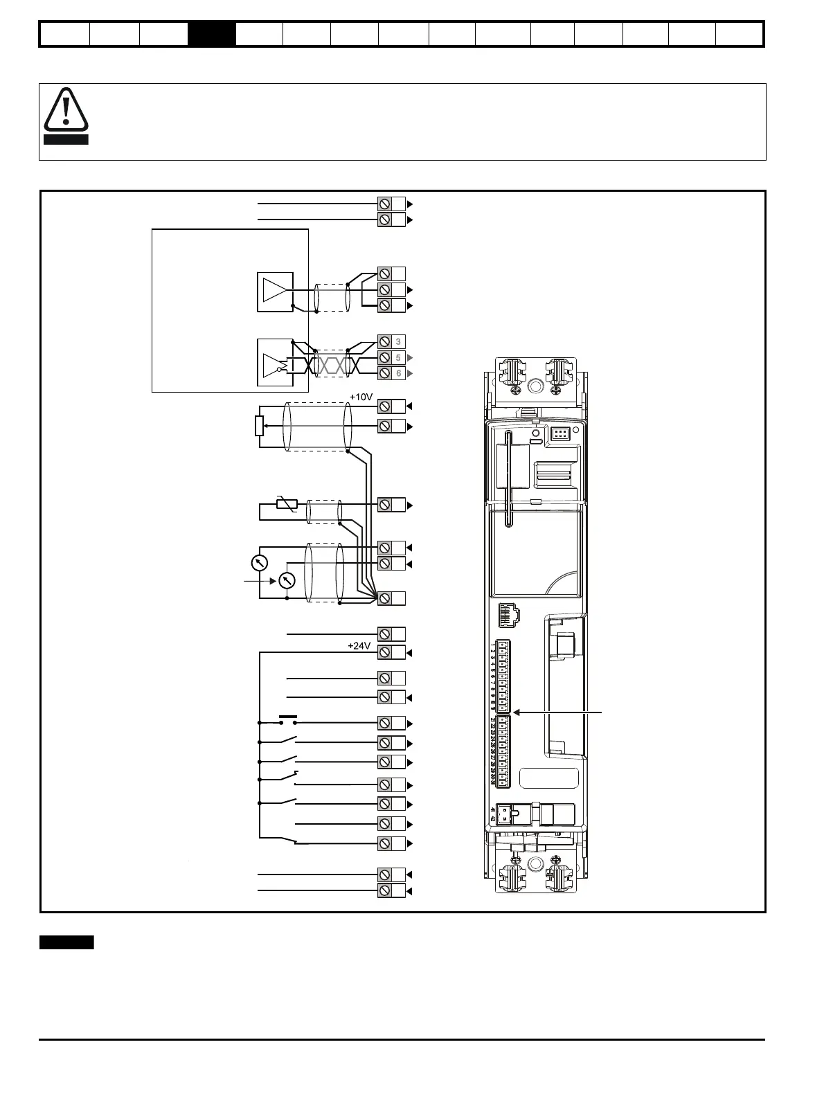
4.14 Control terminals
Figure 4-10 Default terminal functions
For control terminal specification, refer to Chapter 4.14.1 Control terminal specification on page 35.
If Terminal 31 is used as a Safe Torque Off function, the cable must be shielded or segregated.
The control circuits are isolated from the power circuits in the drive by basic insulation (single insulation) only. The installer must ensure
that the external control circuits are insulated from human contact by at least one layer of insulation (supplementary insulation) rated for
use at the AC supply voltage.
0V common
External 24V supply
0V common
Analog speed
reference 1
Connections for
single-ended input
signal
Connections for
differential input signal
0V common
At zero speed
Reset
Run forward
Run reverse
Analog input 1/
input 2 select
SAFE TORQUE OFF
(drive enable)
Status relay
(Overvoltage
category II)
Drive OK
Speed
0V common
Analog
speed
reference 2
4
7
11
9
10
8
Torque (active
current)
Analog input 3
Motor thermistor
Connectors specification:
Maximum size of control
connections cable =
1.5mm (16AWG)
2
Torque setting =
0.2 N m (1.8 lb in)
Status relay cable =
2.5mm (12AWG)
2
Torque setting =
0.5 N m (4.4 lb in)

 Loading...